Topics Covered in This AutoCAD Tutorial:
Master the Multileaders Tools & Command to create professional technical annotations that clearly communicate design intent.
Exercise Preview
This tutorial uses the Multileaders-Desk Lamp.dwg file. You'll work in Paper Space on the B-Sized Layout with the Text layer active throughout the exercise.
Exercise Overview
In this comprehensive exercise, you'll master AutoCAD's powerful Multileaders functionality to create professional annotations with leaders (arrows) that precisely point to specific elements in your technical drawings. This essential skill ensures your drawings communicate design intent clearly and maintain professional standards expected in today's engineering and architectural workflows.
Tutorial Learning Path
Basic Multileader Creation
Create single-line annotations with MLEADER command, snapping to object points and adding text labels
Multi-line Text Integration
Add multiple lines of text within single multileaders for comprehensive annotations
Leader Alignment & Management
Use MLEADERALIGN to organize annotations and manage multiple leaders per annotation
Style Application & Blocks
Apply Tag Multileader Style with block attributes and consolidate multiple annotations
Multileaders
Follow these step-by-step instructions to build expertise with AutoCAD's annotation tools, progressing from basic leader creation to advanced multi-leader management techniques.
Begin by opening the file Multileaders-Desk Lamp.dwg. Navigate to the B-Sized Layout and set your current layer to Text. This setup ensures your annotations are properly organized and will plot correctly on standard drawing sheets.
While working in Paper Space, access the Multileader tool by selecting Leader from the Multileader dropdown menu in the Annotation Panel within the Home tab of the Ribbon. Alternatively, type MLEADER ENTER for keyboard efficiency—a practice that significantly speeds up professional drafting workflows.
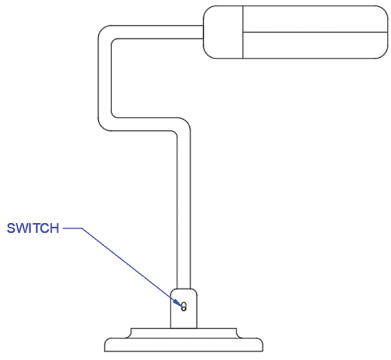
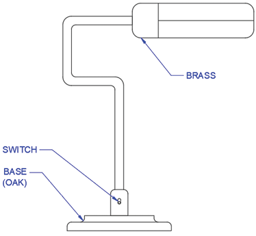
Click precisely on any object snap point located on the left side of the on/off switch, positioned directly above the lamp's base as illustrated below. This demonstrates AutoCAD's intelligent cross-space functionality—even while operating in Paper Space, the Multileader tool seamlessly snaps to Model Space geometry.
Next, click in the area to the left of the lamp to establish the text placement for your Multileader. The Text Editor Ribbon tab will automatically appear, providing formatting options. Type SWITCH in capital letters, following standard drafting conventions for component labels. Press Esc to exit the text editor, then press Enter to finalize your annotation.
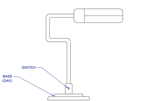
Now you'll create a multi-line annotation within a single Multileader—a technique essential for detailed component specifications. Execute the Multileader command again and click precisely on the left edge of the base as shown below to position the leader arrowhead.
Place the text annotation to the left of the lamp and type BASE, then press Enter to create a second line of text within the same leader. Type (OAK) to specify the material, demonstrating how professional drawings communicate both component identification and material specifications. Press Esc to exit the text editor and Enter to accept the changes.
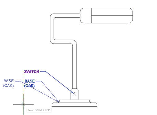
With multiple Multileaders created, you can now align them for professional presentation using the MLEADERALIGN tool. From the Multileader dropdown menu in the Annotation panel, select Align. This powerful alignment feature ensures consistent, readable annotation layouts that meet professional drafting standards.
Select both the SWITCH and BASE multileaders, then press Enter. When prompted to Select Multileader to Align to, choose the SWITCH leader as your reference. A dynamic tracking line will appear from the SWITCH multileader. Position your cursor below the SWITCH multileader until it snaps to the vertical polar tracking line, then click to achieve perfect vertical alignment—a hallmark of professional technical drawings.
Next, you'll explore the Add Leader functionality, which demonstrates why this tool is called the Multileader command. This feature allows multiple arrows to point from a single annotation to various related components—invaluable when annotating assemblies with multiple identical parts.
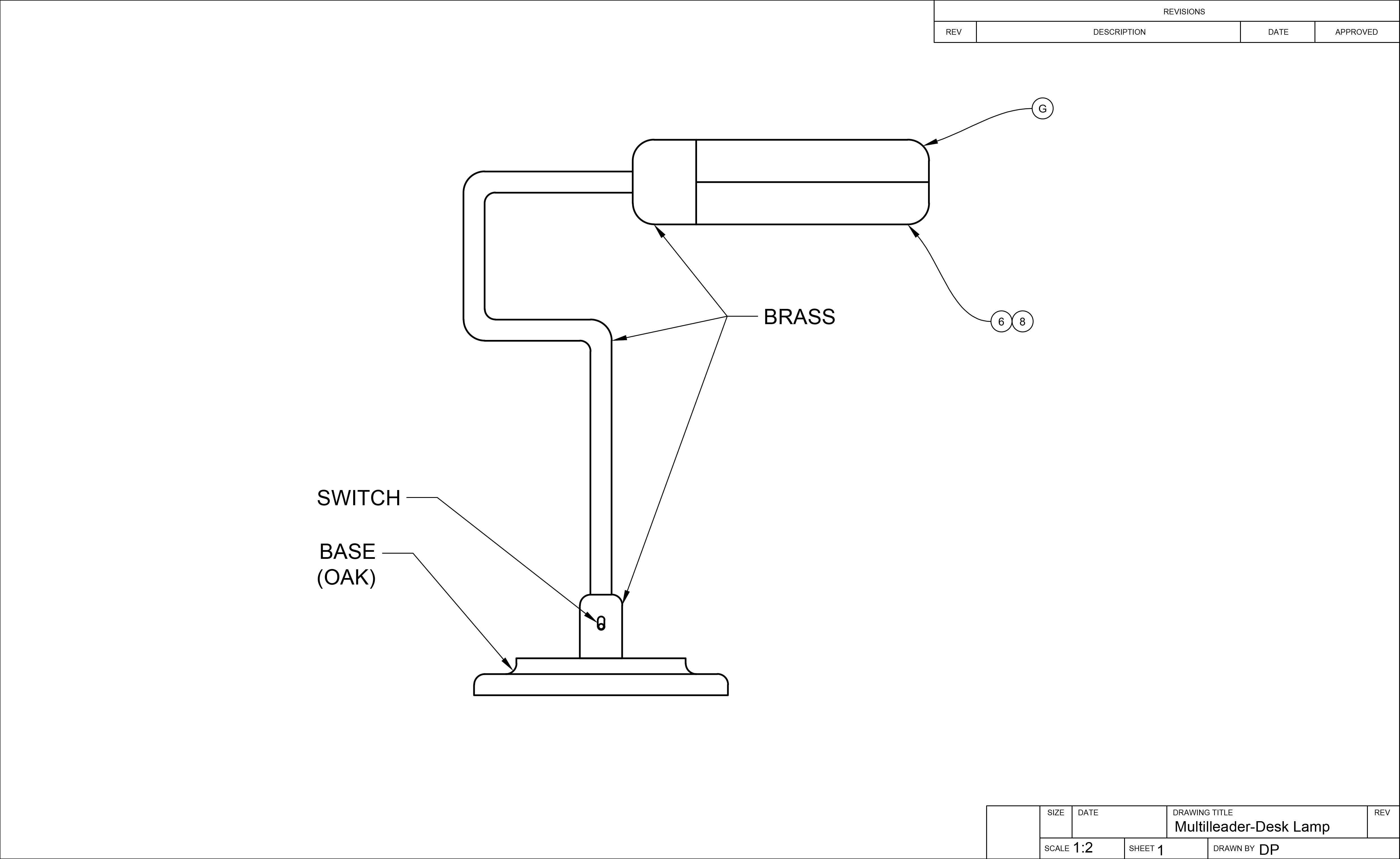
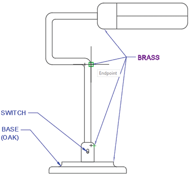
Create a new multileader with the leader snapped to the point shown in the left diagram below. Enter BRASS as the text annotation, then complete the command. This initial leader will serve as the foundation for additional arrows pointing to all brass components.
From the Multileader dropdown menu in the Annotation panel, select Add Leader. Select the BRASS multileader you just created, then systematically click on the three additional points shown in the right diagram below to add corresponding leaders. Press Enter or Esc to complete the command. This technique dramatically reduces annotation clutter while maintaining clear communication.
Create a Multileader with the text "BRASS" with the leader snapped to the point shown below:
Use Add Leader from the Annotation Panel to add 3 more leaders snapped to the points shown below:
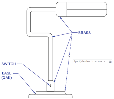
Precision is crucial in technical documentation. You'll notice that one of the leaders from the previous step incorrectly points to the oak base rather than a brass component. The Remove Leader function allows you to correct such errors without recreating entire annotations—a time-saving feature essential for efficient drafting workflows.
Select Remove Leader from the Multileader dropdown menu in the Annotation Panel. This function utilizes the MLEADEREDIT command's removal option. Select the BRASS multileader, and when prompted to Specify leaders to remove, click precisely on the leader arrow pointing to the base. Press Enter to execute the command, and the incorrect leader will be eliminated while preserving the annotation and remaining arrows.
Select Remove Leader from the Annotation Panel and select the leader shown below:
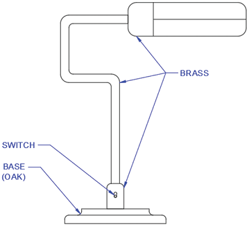
When you complete the Remove Leader command, the selected leaders will be deleted:
Professional AutoCAD workflows leverage Multileader Styles to maintain consistency across projects and meet company standards. These styles define appearance characteristics and can specify whether leaders terminate in text or graphical blocks. While creating custom styles is covered in intermediate AutoCAD training, understanding how to apply existing styles is fundamental for current practice.
Expand the Annotation panel in the Home tab of the Ribbon to reveal dropdown menus for all annotation styles. Locate the Multileader Styles menu (third from the top) and select the Tag Multileader Style. This style represents a common industry approach where leaders terminate in numbered or lettered circles rather than text.
The Tag Multileader Style utilizes a block with a Block Attribute—a text field that accepts user-defined values when the multileader is created. This system is particularly effective for creating drawing legends and coordinated annotation systems. Advanced block creation and attribute management are covered in comprehensive AutoCAD training programs.
With the Tag Multileader Style now active, select Leader from the Multileader dropdown menu in the Annotation panel to initiate the Multileader command.
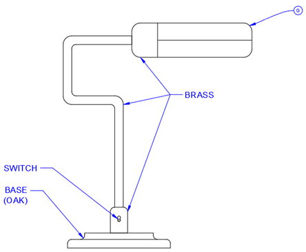
Click an object snap point on the upper section of the rounded rectangle at the lamp's top as illustrated below. The Edit Attributes dialog box will appear automatically. In the Enter tag number field, type G and click OK. The completed leader will terminate in a circle containing the letter G—a clean, professional annotation method widely used in technical drawings.
In complex technical drawings, multiple annotations often reference the same component. AutoCAD's MLEADERCOLLECT command provides an elegant solution by consolidating multiple block-style multileaders into a single leader with multiple tags—reducing visual clutter while maintaining complete information.
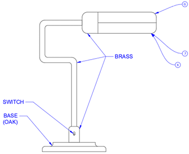
While maintaining the Tag Multileader Style, create two separate multileaders pointing to the identical object snap point on the lower section of the rounded rectangle housing the bulb. Enter the numbers 6 and 7 respectively, as shown in the left diagram below. This simulates a real-world scenario where multiple specifications or notes reference the same component.
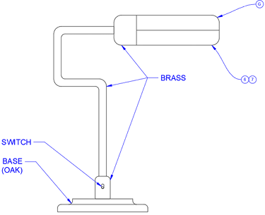
From the Multileader dropdown menu in the Annotation Panel, select Collect to initiate the MLEADERCOLLECT command. Selection order is critical for proper tag arrangement—select the multileaders labeled 6 and 7 in numerical sequence, then press Enter. The circular blocks will automatically consolidate onto a single leader line. Click to position this consolidated leader anywhere below the bulb area.
Create two multileaders with Tag Style and enter the values 6 and 7. Ensure both leaders snap to the identical point as shown below:
Execute the MLEADERCOLLECT command. Select multileaders 6 and 7 in sequence and press Enter. The circular blocks will be consolidated into one leader:
Editing block attributes is straightforward and essential for maintaining accurate documentation. When errors occur in tag values or specifications change during design development, AutoCAD provides quick correction methods without requiring complete recreation of annotations.
Double-click directly on the circular block containing the number 7. The Edit Attributes dialog box will appear, providing access to the tag's text value. Change the 7 to an 8 and click OK. The correction will immediately appear in your multileader, demonstrating AutoCAD's dynamic updating capabilities. Save and close the file to preserve your work.
Even while working in Paper Space, the Multileader tool allows you to snap directly to Model Space objects, providing flexibility in annotation placement.
Creating Your First Multileader
Ensures you have the correct drawing setup for the exercise
Provides proper paper space environment for annotation work
Organizes annotations on appropriate layer for drawing management
Can also type MLEADER ENTER for keyboard access
Uses AutoCAD's object snap system for accurate annotation positioning
Multi-line Text Creation Process
Start Multileader Command
Click on object snap point where leader arrow should point, then place text location
Enter First Line Text
Type your first line of text when Text Editor appears, such as BASE
Add Second Line
Press Enter to create new line, then type additional text like (OAK)
Complete Entry
Press Esc to exit text editor, then Enter to accept all changes
When using Add Leader, always verify that each leader points to the correct material or component. Use Remove Leader to delete incorrectly placed or inappropriate leader arrows.
Multileader Styles Comparison
| Feature | Text Style | Tag Style |
|---|---|---|
| End Result | Text annotation | Block with attribute |
| Leader Appearance | Straight lines | Can be splined/curved |
| Text Input | Direct typing | Attribute dialog box |
| Consolidation | Limited options | MLEADERCOLLECT compatible |
MLEADERCOLLECT Workflow
Create Individual Multileaders
Create separate multileaders with Tag Style, pointing to same location with different values (like 6 and 7)
Start Collection Command
Choose Collect from Multileader dropdown to activate MLEADERCOLLECT command
Select in Proper Order
Select multileaders in the numerical order you want them displayed (6 first, then 7)
Position Consolidated Leader
Click to place the new consolidated leader showing both values in connected blocks
Double-click any multileader block to open the Edit Attributes dialog. This allows you to quickly correct text values without recreating the entire annotation.