Topics Covered in This AutoCAD Tutorial:
The Ellipse Tool, the Polygon Tool
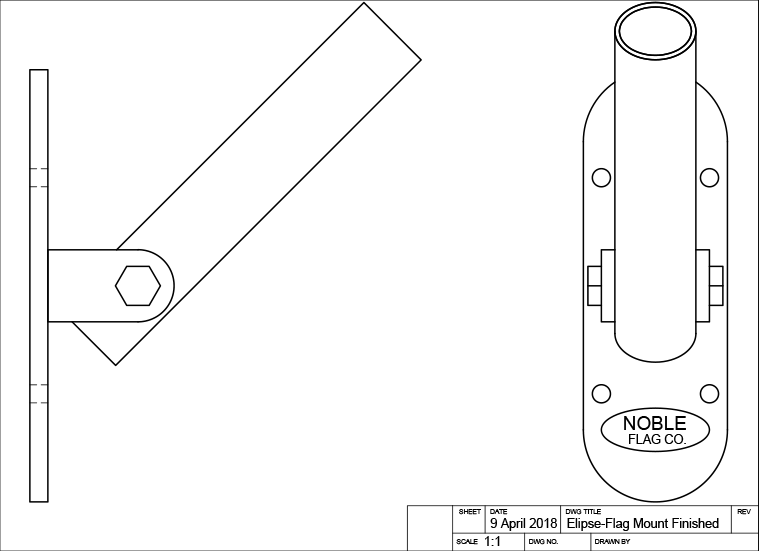
Exercise Preview
Exercise Overview
In this comprehensive exercise, you'll master two essential AutoCAD drawing tools that are fundamental to technical drafting and design work. You'll learn to create precise ellipses and elliptical arcs using the ELLIPSE (EL) Command, including advanced techniques like rotation angles for 3D projections. These skills are particularly valuable for mechanical drawings, architectural details, and any design work involving cylindrical objects viewed at angles.
This hands-on exercise demonstrates real-world applications including creating ellipses around logos, completing angled tube drawings, and drawing mechanical bolts using the polygon tool.
Where to Access the Ellipse Tool
AutoCAD provides multiple pathways to access the Ellipse tool, giving you flexibility in your workflow. You can enter commands directly through the keyboard via the Command Line for maximum speed, utilize the intuitive Ellipse dropdown menu in the Draw Panel on the Ribbon for visual selection, or access options through the traditional Draw menu. Professional drafters often prefer keyboard shortcuts for efficiency, but newer users may find the ribbon interface more approachable.


Ellipse Tool Access Methods
Command Line
Type EL and press Enter for quick keyboard access. Most efficient method for experienced users.
Ribbon Interface
Navigate to Draw Panel on the Ribbon and use the Ellipse dropdown menu for visual selection.
Draw Menu
Access ellipse options through the traditional Draw menu in the menu bar for comprehensive options.
Using the Ellipse Tool
Now we'll put the Ellipse tool into practice with a real-world mechanical drawing scenario. This hands-on approach will demonstrate how ellipses are crucial for representing circular objects in orthographic projections.
Open the file Ellipse-Flag Mount.dwg.
Begin by creating an ellipse around the Noble Flag Co. Logo. Since the logo's text elements will interfere with Object Snap precision during ellipse creation, you'll need to temporarily hide them. Start the Layer Freeze tool and click on the logo to freeze the Text layer, effectively hiding the logo from view. This technique of managing layer visibility is essential for maintaining accuracy in complex drawings.
Select the Center option on the Ellipse tool
 . Understanding ellipse geometry is crucial here: an ellipse has two axes (major and minor), and using the Center option means your first axis will be defined as a radius extending from the center to the edge. Click on the center point of the bottom arc in the front view to establish the ellipse center. Pull horizontally along the X-axis and enter a radius of .75. Keep the Ellipse command active for the next step.
TIP: Click on the center point of the bottom arc to start the first axis of the ellipse.
Now complete the ellipse by pulling vertically along the Y-axis and entering a radius of .3. This creates the second axis and completes your ellipse. Remember that the Axis, End (default), and Center options control how you define the first axis, while the second axis is always established as a radius from the center—unless you choose the Rotation option, which we'll explore next.

Use the Layer Previous Command to unfreeze the Text layer and restore the Noble logo to visibility. This workflow of freezing and unfreezing layers is a professional best practice for managing complex drawings.
Next, you'll tackle a more advanced application: using the Ellipse tool
to represent the circular opening of a tube viewed at an angle. The tube is positioned at 45°, so the ellipse must accurately represent how a circle appears when tilted at this angle—a common challenge in technical drawings. This requires the Rotation option.Type EL Enter to start the Ellipse command, or select Axis, End from the Ellipse
dropdown in the Draw panel. Axis, End is the default setting, so it won't appear as a selectable option in the Command Line. This method establishes the first axis diameter by clicking from one end to the other.Snap precisely to the endpoint of either edge at the tube's top, then click the opposite endpoint to define the first axis. Once this axis is established, the Rotation option becomes available in the Command Line. Press R Enter to activate it.

With the Rotation option active, you can specify an angle that will make the ellipse accurately represent a circle tilted at that precise angle—this is fundamental to creating accurate orthographic projections. Since the flagpole mount tube is angled at 45°, enter 45 Enter or click along a 45° tracking line. Notice how the resulting ellipse at the tube's top aligns perfectly with the drawing's side view—this demonstrates proper orthographic projection principles.

To create the tube's inner wall thickness, press O Enter to start the Offset Command. Enter an offset distance of .0625 (1/16 inch—a standard wall thickness in many applications) and select the ellipse you just created. Click anywhere inside the ellipse to specify which side to offset toward. Press Enter or Escape to complete the Offset command. This technique efficiently creates parallel geometry with precise spacing.

TIP: Offset the ellipse on the inside by .0625 to make the inner edge.
Compare your front and side views to verify accuracy. The ellipse represents exactly how the circular tube appears when viewed from the front at a 45° angle—a perfect example of how AutoCAD's geometric precision supports proper technical drawing standards.

Now you'll create an Elliptical Arc to complete the tube representation. An Elliptical Arc uses a portion of an ellipse—think of it as cutting a slice from an elliptical "pie." This tool is invaluable for representing partial views of cylindrical objects or curved transitions in mechanical parts.
When you select the Arc option on the Ellipse tool, you'll follow the standard ellipse creation process, but finish by defining which portion of the ellipse to retain as your arc. The remainder is automatically deleted.
Press EL Enter to start the Ellipse command, then A Enter for the Arc option, or select Elliptical Arc from the Ellipse
dropdown in the Draw panel. Snap to either endpoint at the tube's bottom and repeat your previous steps: create the ellipse using the Rotation option with a 45° angle.The Command Line will prompt for a start angle—this defines your arc boundaries. Since AutoCAD measures angles counter-clockwise by default, snap to the left endpoint, then move your cursor counter-clockwise to the opposite endpoint and click. Notice how the preview line follows your cursor movement, visually showing the arc portion you're selecting.

Creating an Ellipse Around a Logo
Prepare the Drawing
Open Ellipse-Flag Mount.dwg and use Layer Freeze tool to hide the logo that would interfere with Object Snap
Set Center Point
Select Center option and click on the center point of the bottom arc in the front view
Define First Axis
Pull along X-axis and enter radius of 0.75 for the horizontal dimension
Complete Second Axis
Pull along Y-axis and enter radius of 0.3 to complete the ellipse
The Axis, End (default), and Center options determine how you create the first axis. The second axis is always a radius from center unless you use the Rotation option.
Creating Angled Tube Ellipse with Rotation
Start Ellipse Command
Use EL Enter or select Axis, End from the Ellipse dropdown menu
Define First Axis
Click endpoint to endpoint at the top of the tube to establish the diameter
Apply Rotation
Press R Enter to activate Rotation option and enter 45 degrees for the tube angle
Create Inner Edge
Use Offset Command with 0.0625 distance to create the inner tube wall
Using the Polygon Tool
Moving from curved geometry to angular precision, we'll now explore the Polygon tool. This tool is essential for creating regular polygons like hexagonal bolt heads, octagonal features, or any design element requiring equal sides and angles.
You'll use the Polygon tool
 to create the hexagonal bolt head in the side view—a common mechanical element that requires precise geometric accuracy. Type POL Enter, select Polygon from the Rectangle dropdown in the Draw panel, or click the Polygon button in the Draw Toolbar.
When prompted for the number of sides, enter 6 to create a hexagon—the standard shape for bolt heads and nuts in mechanical applications. Click on the center point of the arc at the bracket's end in the front view to establish the polygon's center point, as shown below.

AutoCAD will prompt you to choose between Inscribed or Circumscribed options. This choice determines how the polygon relates to an imaginary reference circle. Inscribed means the polygon fits inside the circle (vertices touch the circle), while Circumscribed means the polygon contains the circle (sides are tangent to the circle). For bolt heads, inscribed is typically preferred as it represents the actual dimension across flats.
Pull horizontally along the X-axis and enter a radius of .3125, creating a standard 5/8-inch bolt representation. This dimension follows ANSI/ASME standards for mechanical fasteners. Note that you can also use the Edge option to specify exact side lengths, which we'll cover in subsequent exercises.

Close and save the file to preserve your work. You've now mastered two fundamental AutoCAD tools that are essential for technical drawing and design work.
Creating a Hexagonal Bolt
Start Polygon Command
Type POL Enter or select Polygon from Rectangle dropdown in Draw panel
Set Side Count
Enter 6 for the number of sides to create a hexagonal bolt head
Position Center Point
Click on the center point of the arc at the end of the bracket in front view
Define Size
Choose Inscribed or Circumscribed and enter radius of 0.3125 for standard 5/8 inch bolt
Polygon Sizing Options
| Feature | Inscribed | Circumscribed |
|---|---|---|
| Position | Inside imaginary circle | Outside imaginary circle |
| Radius Input | From center to vertex | From center to side |
| Alternative Method | Edge option for specific side length | Edge option for specific side length |