Topics Covered in This AutoCAD Tutorial:
Join Command
Exercise Preview

This tutorial requires the Join-Brace.dwg file. Ensure you have this file ready before beginning the exercise steps.
Exercise Overview
In this hands-on exercise, you'll master the Join command—one of AutoCAD's most essential tools for maintaining drawing integrity. You'll learn to reconnect straight line segments after removing unwanted geometry, a common workflow when refining technical drawings or preparing files for manufacturing. This skill is particularly crucial for professionals working with CNC machining, laser cutting, or other automated fabrication processes where segmented lines can cause costly production errors.
Join Command Exercise Workflow
Open and Prepare Drawing
Open Join-Brace.dwg file and delete the two curved line segments in the center to create gaps in the drawing
Reconnect Bottom Edges
Use Move tool to select right half objects and reconnect bottom edges by matching endpoints together
Apply Join Command
Execute JOIN command to connect disconnected segments into unified lines for manufacturing compatibility
The Join Command
Open the file Join-Brace.dwg.
Select and delete the two curved line segments in the center of the object as shown below. Use standard selection methods—either click each segment individually while holding Shift, or create a selection window around both curves.
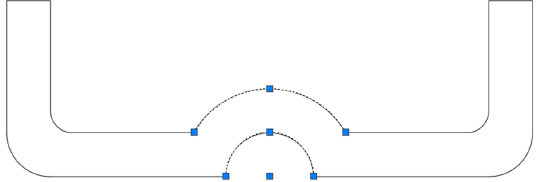
After deletion, your drawing should match the configuration below. Notice how removing these segments has created gaps that will need to be addressed:

Now you'll reconnect the geometry using precise endpoint snaps. Start the Move tool and select all objects on the right half of the drawing. Click the bottom left endpoint as your base point, then connect it precisely to the corresponding endpoint of the bottom line on the left side. This step demonstrates the importance of geometric precision—AutoCAD's object snaps ensure perfect alignment, which is essential for the Join command to function properly.

Execute the Join command by typing JOIN Enter or clicking the Join button
 in the extended Modify panel. Select the two disconnected top edge segments and press Enter. AutoCAD will merge them into a single, continuous line object.
Understanding the Join command's behavior is critical for professional workflows: When line segments are not touching, Join can only merge straight segments that are perfectly collinear—meaning they align to form a continuous straight line. However, when segments share endpoints, Join can connect both straight and curved elements seamlessly. This flexibility makes it invaluable for cleaning up imported geometry or drawings that have been extensively modified.
The bottom edge remains divided into two separate line segments—a common issue that can have serious downstream consequences. While this segmentation might not affect standard plotting or printing, it creates significant problems for automated manufacturing processes. CNC machines, laser cutters, waterjet systems, and 3D printers often interpret segmented lines as separate tool paths, leading to inefficient operations, visible seam marks, or complete fabrication failures. Modern manufacturing workflows in 2026 increasingly rely on clean, continuous geometry for optimal results.
Press Enter to restart the Join command and select both bottom edge segments. After joining, clicking anywhere on the bottom edge will select the entire line as a single object—confirming successful consolidation. For complex drawings, consider using the OVERKILL command in conjunction with Join to eliminate duplicate geometry and optimize file performance.

Save and close the file using Ctrl+S followed by Ctrl+W, or use the Application Menu if you prefer. Your drawing now contains optimized geometry suitable for both traditional drafting applications and modern digital manufacturing workflows.
Access the Join command by typing JOIN and pressing Enter, or click the Join button in the extended Modify panel or toolbar.
Join Command Capabilities
Before vs After Join Command
| Feature | Before Joining | After Joining |
|---|---|---|
| Line Segments | Multiple disconnected pieces | Single fluid line |
| Object Selection | Selects individual segments | Selects entire unified object |
| Manufacturing | May cause CNC issues | Compatible with automation |
| File Organization | Multiple objects to manage | Single organized object |
Disconnected segments can cause problems for CNC machines, cutters, and automatic fabrication equipment, leading to wasted time and materials.
Join Command Best Practices
Join command requires proper alignment for successful connection
Multiple segments can be joined in a single command execution
Ensures successful joining and manufacturing compatibility
Preserves your work and maintains drawing integrity