Topics Covered in This AutoCAD Tutorial:
Master the fundamentals of the Line Command — the cornerstone of precise technical drawing
Exercise Preview
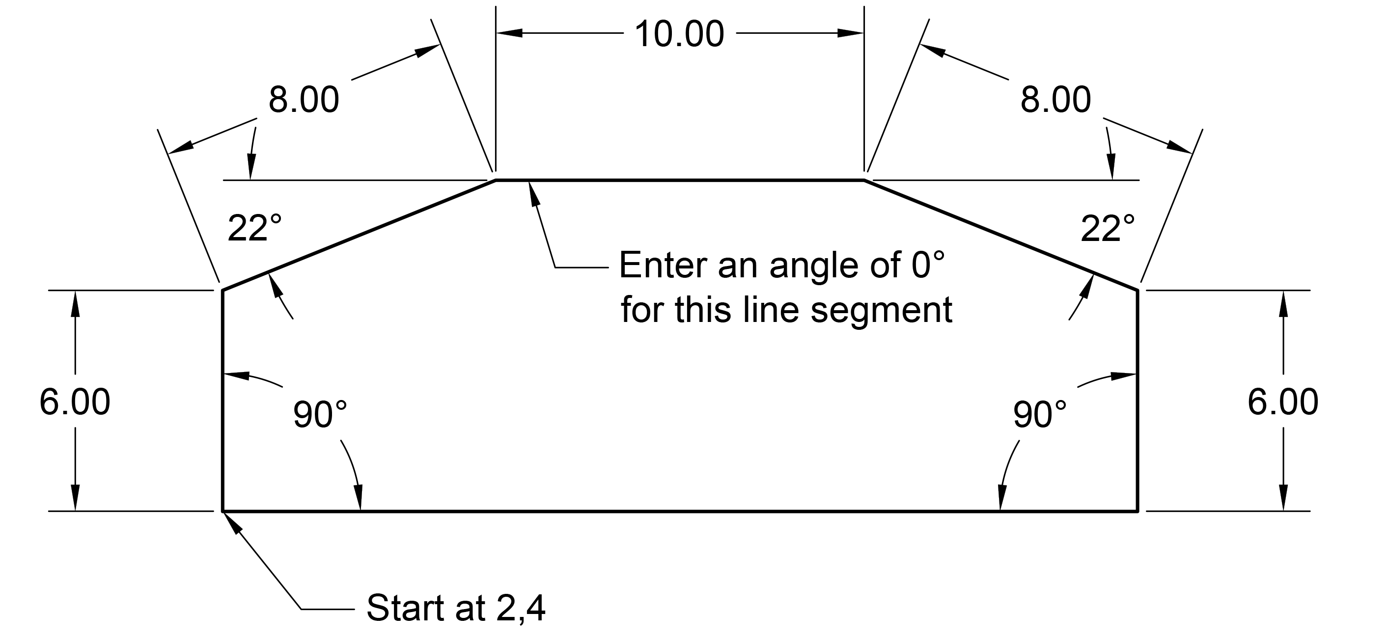
You'll create a complete geometric shape using precise measurements and angles, demonstrating real-world drafting techniques used by professionals.
Exercise Overview
The Line Command forms the foundation of virtually every technical drawing you'll create in AutoCAD. In this comprehensive exercise, you'll master the precise art of drawing straight lines using coordinate input, distance specifications, and angular control. More importantly, you'll develop fluency with AutoCAD's Command Line interface — a skill that separates efficient professionals from casual users. By the end of this tutorial, you'll understand how professional drafters achieve pixel-perfect accuracy in their technical drawings, creating the geometric shape shown above with mathematical precision.
Getting Started
Let's establish your workspace and prepare AutoCAD for precision drawing. These initial steps ensure you're working with optimal settings from the start.
- If AutoCAD isn't already open, launch it now.
- You should see the Start tab with its familiar interface.
Click on the large Start Drawing button to create a new document.
A fresh Drawing1 tab will open, ready for your work. AutoCAD drawing files use the industry-standard .dwg file format and are built upon Drawing Template files (.dwt). While we'll use the default template for this exercise, understanding template customization becomes crucial as you advance in your AutoCAD proficiency — we'll explore this powerful feature in upcoming lessons.
Initial Setup Process
Launch AutoCAD
Open the application and navigate to the Start tab interface
Create New Drawing
Click the Start Drawing button to open a new Drawing1 tab with default template
Configure Status Bar
Disable Polar Tracking and ORTHOMODE by ensuring they're not highlighted in blue
Using the Line Command
Now we'll dive into the practical application of AutoCAD's most fundamental drawing tool. Pay careful attention to the Command Line feedback — this real-time communication with AutoCAD is essential for professional-level precision.
Direct your attention to the Status Bar in the lower right corner of your screen.
This control panel houses toggle buttons for AutoCAD's most frequently used drafting aids. When active, these buttons display a distinctive blue highlight. Understanding these tools transforms your drawing efficiency, but for now we need a clean slate to learn fundamental line creation.
- Ensure both Polar Tracking
 and ORTHOMODE
  are disabled (not highlighted in blue). If either shows blue highlighting, click to deactivate it. These powerful drafting aids will be covered thoroughly in our next exercise, where you'll discover how they accelerate professional workflow.
 - Initiate your first line by clicking the Line tool
 in the Ribbon panel at the top of your screen.
 Notice how selecting the tool immediately activates the Command Line panel at the bottom of your screen.
Status Bar ConfigurationAlways check the Status Bar settings before starting. Disabled Polar Tracking and ORTHOMODE give you full control over line direction and angles.
Key Interface Elements
Ribbon Panel
Located at the top of the screen, contains the Line tool as the first option. This is your primary tool palette for drawing commands.
Status Bar
Found in the lower right corner with blue highlighting for active features. Controls drawing aids and precision tools.
The Command Line
The Command Line serves as AutoCAD's primary communication hub — think of it as an ongoing conversation between you and the software. Every mouse click, keyboard input, and tool selection appears here, along with current command status and available options. Professional AutoCAD users develop the habit of constantly monitoring this feedback. This awareness dramatically improves accuracy, reduces errors, and reveals advanced options that casual users often miss. Master the Command Line, and you'll work with the confidence of a seasoned professional.
AutoCAD drawing commands typically begin by requesting a starting point. While clicking with your mouse provides approximate coordinates, professional work demands precision through direct coordinate entry:
Establish the foundation point for our geometric shape by typing the precise coordinates. Press 2, then comma (, ), then 4 to input 2,4 in the command line:

Press Enter to confirm and apply these starting coordinates.
Move your mouse cursor upward to establish the directional intent for your next line segment.
IMPORTANT: AutoCAD requires directional input before accepting distance and angle values. This mouse movement doesn't determine the final line direction — it simply tells AutoCAD which quadrant you're working toward. Think of it as pointing AutoCAD in the right neighborhood before providing exact specifications.
Specify the exact line length by typing 6, then press Tab to advance to the angle input field.
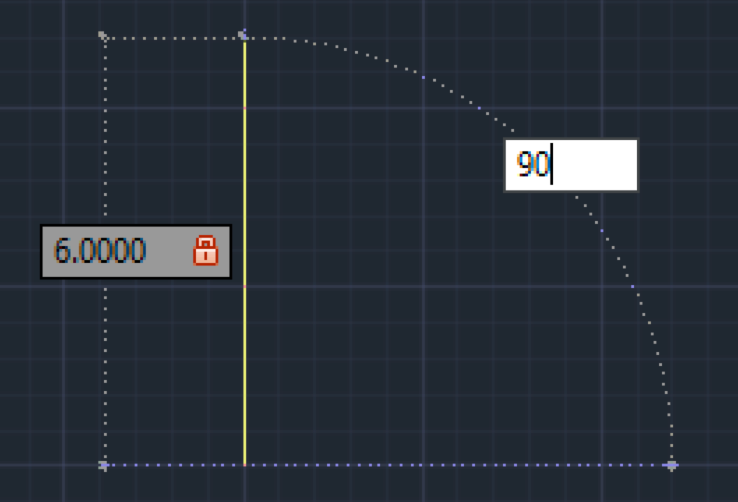
For a perfectly vertical line, enter 90 degrees and press Enter. Congratulations — you've just created your first precisely controlled line segment using professional coordinate input methods!
Continue building the geometric shape with the angled top-left corner segment:
- Point your cursor toward the right to indicate general direction.
- Type 8 units for the distance measurement.
- Press Tab to move to the angle field.
- Enter 22 degrees for the precise angle.
- Press Enter to complete this line segment.
Create the horizontal top edge of your shape:
- Move your cursor toward the right.
- Input 10 units for distance.
- Press Tab to access the angle field.
- Enter 0 degrees for a perfectly horizontal line.
- Press Enter to finish this segment.
Add the angled top-right corner with these specifications:
- Point your cursor toward the right.
- Type 8 units for distance.
- Press Tab to advance to angle input.
- Enter 22 degrees.
- Press Enter to complete the segment.
Form the vertical right edge of your geometric shape:
- Direct your cursor downward.
- Input 6 units for distance.
- Press Tab for angle specification.
- Enter 90 degrees for perfect vertical alignment.
- Press Enter to finish this segment.
Save the file as my first line drawing.dwg and click Save.
The Command Line shows your current command, its stage, and available options. Paying attention to this panel is essential for AutoCAD proficiency.
Drawing the Complete Shape
Set Starting Point
Type coordinate 2,4 and press Enter to establish the precise starting location
First Vertical Line
Move cursor upward, enter distance 6, press Tab, enter angle 90 degrees, press Enter
Angled Corner
Move cursor right, enter distance 8, press Tab, enter angle 22 degrees, press Enter
Horizontal Top
Move cursor right, enter distance 10, press Tab, enter angle 0 degrees, press Enter
Complete and Close
Continue with remaining segments, then use Close option to finish the shape automatically
Coordinate Input Methods
Essential Workflow Steps
AutoCAD needs directional context before accepting distance values
Efficiently moves between distance and angle input without mouse clicks
Completes the current segment and prepares for the next one
Proper file management prevents work loss and aids project organization