Topics Covered in This AutoCAD Tutorial:
Mastering the Circle Commands and Their Professional Applications
Skills You'll Master
Learn the default method for drawing circles with precise measurements
Create circles by defining two points that establish the diameter
Draw circles tangent to two objects with specified radius
Create circles that touch three existing objects simultaneously
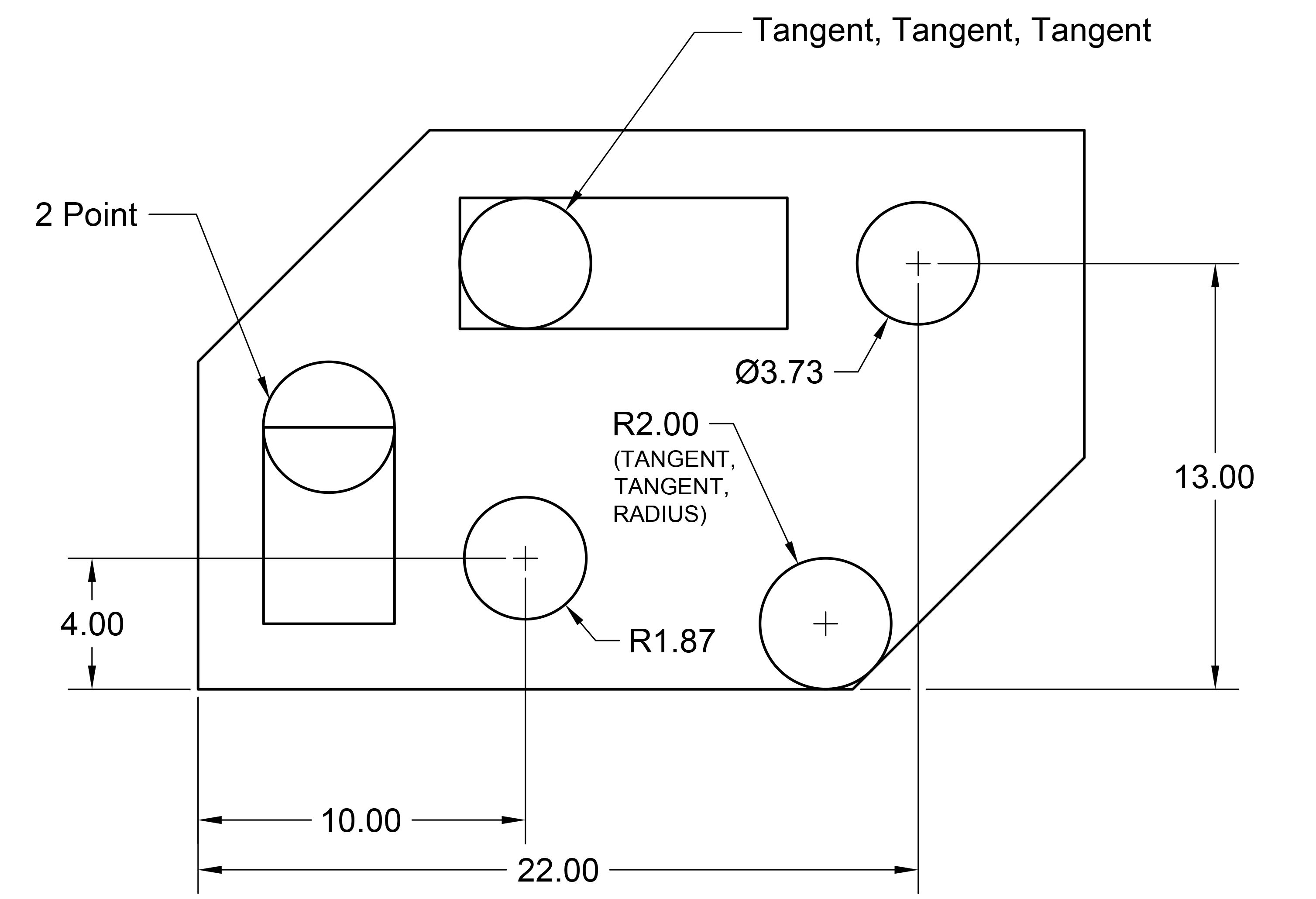
Exercise Preview
Exercise Overview
The Circle Command is one of AutoCAD's most versatile drawing tools, offering multiple methods to create precise circular geometry tailored to different design scenarios. In this comprehensive exercise, you'll master four essential circle creation methods: the Center-Radius approach for basic circular elements, the 2-Point method for fitting circles to existing geometry, the Tan-Tan-Radius technique for mechanical design applications, and the Tan-Tan-Tan method for complex tangential relationships. Understanding when and how to apply each method will significantly enhance your drafting efficiency and precision in professional CAD work.
The Circle Command options are available in multiple locations: Command Line interface, Draw Menu, and the dropdown Circle Command menu in the Draw Panel on the Home Tab of the Ribbon.
Circle Creation Workflow
Access Circle Tool
Click the Circle tool in the top Ribbon panel or use the dropdown for advanced methods
Choose Method
Select from Center/Radius, 2-Point, or tangent-based methods depending on your needs
Define Parameters
Specify center points, radii, diameters, or tangent objects as required by chosen method
Complete Circle
Press Enter to execute the command and create the circle geometry
The Circle Command
Let's dive into the practical application of each circle creation method, starting with the most fundamental approach and progressing to more specialized techniques.
To initiate circle creation, navigate to the Ribbon panel and click the Circle tool
 to activate the Circle Command. This tool remains consistently positioned in the Draw panel across all recent AutoCAD versions, making it easily accessible for frequent use.
The Center, Radius method serves as the default approach because it mirrors how we typically conceptualize circles in design work. For our first circle, establish the center point by entering the coordinates 22,13. While you can click to specify the center point visually, coordinate entry ensures mathematical precision—critical for professional drafting standards.
Once you've defined the center point, AutoCAD displays the Diameter option in the Command Line, giving you flexibility in how you specify the circle's size. Press D followed by Enter to select the Diameter option, which is often more intuitive when working with mechanical components or architectural elements.
Enter a diameter value of 3.73. This precise measurement demonstrates how AutoCAD handles decimal values, maintaining accuracy to multiple decimal places—essential for manufacturing and construction applications.
Press Enter to repeat the Circle Command. AutoCAD's command repetition feature streamlines workflow when creating multiple similar elements, a common requirement in professional drafting.
Specify the center point coordinates 10,4 for your second circle. Notice how establishing a systematic approach to coordinate entry builds consistency in your drafting methodology.
AutoCAD intelligently displays the previous circle's radius in the Command Line within angle brackets. Press Enter to accept the default radius (
<1.87>), demonstrating how the software remembers your last input to accelerate repetitive tasks—a significant productivity advantage in complex drawings.Press Enter once more to repeat the Circle Command, transitioning to explore alternative circle creation methods that offer greater geometric flexibility.
In the Command Line, select 2P to activate the 2-Point method, which excels when you need to fit circles precisely between existing geometric elements.
NOTE: The 2-Point (2P) method calculates circle diameter by using two specified points as diameter endpoints, making it invaluable for fitting circles to existing geometry. The 3-Point (3P) method creates circles that pass through three designated points, useful for complex geometric relationships and circular interpolation between multiple reference points.
To create a circle that perfectly aligns with the top edge of the left rectangle, position your cursor over the top-left corner. When the green square snap symbol appears, click to establish the first diameter point. AutoCAD's object snap system ensures precise alignment with existing geometry—a cornerstone of professional CAD practice.
Navigate your cursor to the top-right corner of the rectangle, allowing the snap system to lock onto the corner point. Click to complete the circle creation, resulting in a circle whose diameter precisely matches the rectangle's width. This method proves invaluable when designing components that must integrate seamlessly with existing geometry.
To demonstrate advanced tangent-based circle creation, press Enter to repeat the Circle Command and explore methods particularly useful in mechanical design and architectural detailing.
Tangent-based circle creation leverages geometric relationships where circles touch other objects at precisely one point. The Tan-Tan-Radius (Ttr) method requires you to specify two objects the circle will touch, plus a radius value, making it essential for mechanical components, pipe routing, and architectural details.
Access this specialized tool by clicking the dropdown arrow beneath the Circle tool in the Ribbon menu, then selecting Tan, Tan, Radius (Ttr). This method streamlines the creation of circles that must maintain specific tangential relationships with existing geometry.
NOTE: These tangent options appear in multiple interface locations—the Command Line, Draw Menu, and the Circle Command dropdown in the Draw Panel—providing flexibility in how you access these tools based on your workflow preferences.
Click on the bottom edge and lower right edge of your drawing to define the tangent relationships for your circle. Watch for the tangent snap symbol—a small circle with a tangent line—which confirms proper object selection. Press ENTER to accept the default radius value of <2>, creating a circle that touches both selected objects tangentially. This technique is fundamental in mechanical design for creating smooth transitions and in architectural work for designing curved elements that integrate seamlessly with straight segments.
The Tan, Tan, Tan method represents the most sophisticated circle creation technique, automatically calculating a circle that touches three specified objects simultaneously. This powerful tool, accessible exclusively through the Circle Command dropdown menu in the ribbon, proves invaluable for complex geometric situations such as creating circles that fit within triangular spaces or connecting three separate design elements with smooth curves. Professional drafters frequently employ this method in mechanical assemblies, architectural details, and civil engineering applications where multiple tangential relationships must be satisfied simultaneously.
Circle Creation Methods Comparison
| Feature | Method | Best Use Case |
|---|---|---|
| Center, Radius | Standard circles with known center | General purpose drawing |
| 2-Point | Circles fitting between points | Diameter-based design |
| Tan, Tan, Radius | Circles touching two objects | Filleting with curves |
| Tan, Tan, Tan | Circles inscribed in triangles | Complex tangent relationships |
You can either type exact coordinates like 22,13 for precise placement, or click on points in the drawing area for interactive positioning. Coordinate entry ensures accuracy for technical drawings.
The Tan, Tan, Tan option is only available in the Circle Command dropdown menu in the ribbon, and not accessible through the command line interface.
A tangent is the point at which a circle or curve touches another object.