Topics Covered in This AutoCAD Tutorial:
Mastering Block Insertion and the Insert Command – Essential Skills for Professional CAD Workflows
Exercise Preview
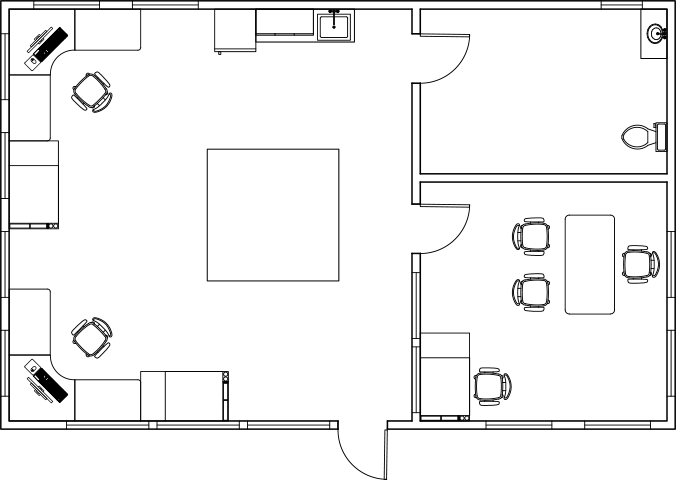
This exercise guides you through furnishing a complete studio apartment using various AutoCAD blocks including refrigerators, desks, chairs, and drafting tables with proper positioning and orientation.
Exercise Overview
In this comprehensive exercise, you'll master the fundamentals of inserting blocks using AutoCAD's Insert command. Block insertion is a cornerstone of efficient CAD practice, enabling you to maintain consistency across drawings while dramatically reducing drafting time. You'll learn not only the mechanics of placement, but also the strategic considerations that separate novice users from seasoned professionals.
Block Insertion Workflow
Access Insert Command
Use the Insert dropdown in the Home Tab Ribbon or press 'I' + Enter for the keyboard alias to open insertion options.
Select and Configure Block
Choose your block from the available list, adjust scale and rotation parameters using the Insert dialog box as needed.
Place with Precision
Position the block using its base point, utilizing object snaps and polar tracking for accurate placement in your drawing.
Inserting Blocks with the Insert Command
Begin by opening the file Blocks-Studio.dwg. This drawing contains a studio apartment layout that we'll furnish using various block insertion techniques.
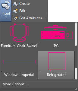
Navigate to the Block Panel within the Home tab of the Ribbon interface. Expand the Insert dropdown menu to reveal available blocks. Notice that blocks previously inserted in this drawing remain accessible even if they've been deleted from the current view – this is because blocks become permanently attached to the drawing file upon first insertion, creating a reusable library. Select the Refrigerator block from the available options.
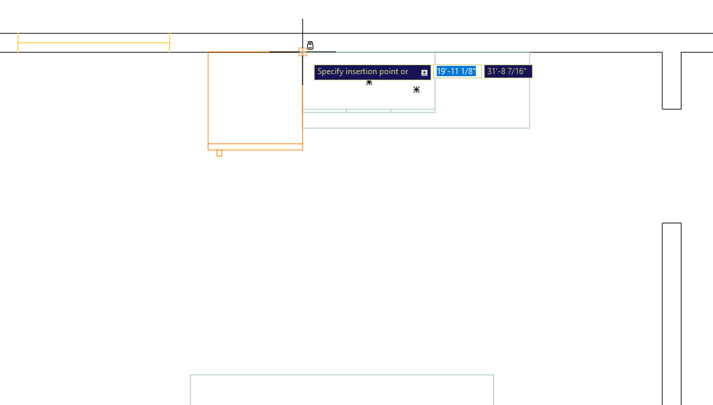
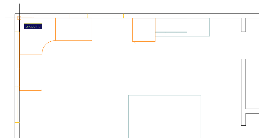
Understanding base points is crucial for precise block placement. Each block has a predetermined base point established during creation – for this refrigerator block, it's located at the upper-right corner. This base point serves as your insertion anchor and directly impacts placement accuracy. Monitor the command line for orientation options if adjustments are needed. Position the refrigerator by clicking to place its base point at the upper-left corner of the counter in the studio's upper-right area, as demonstrated in the diagram below.
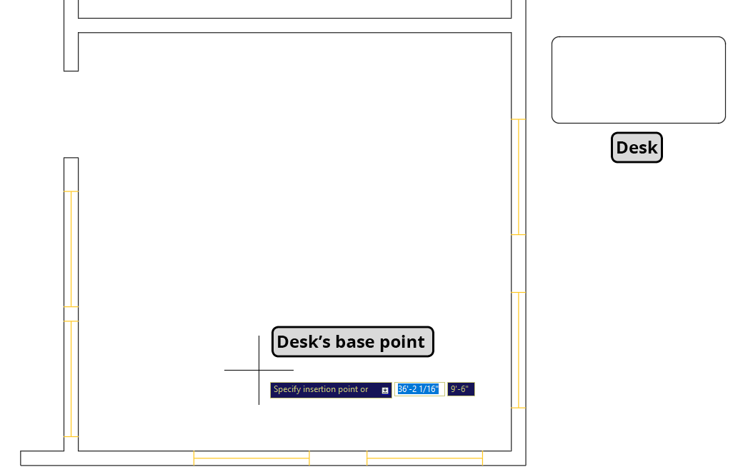
Next, we'll position a corner desk in the studio's upper-left area. Return to the Insert menu and locate the Furniture-Desk-Corner block. You'll notice its current orientation doesn't suit our placement needs – this is a common scenario in professional practice. Click the More Options button at the bottom of the expanded panel to access the comprehensive Insert dialog box, which provides full control over block properties.
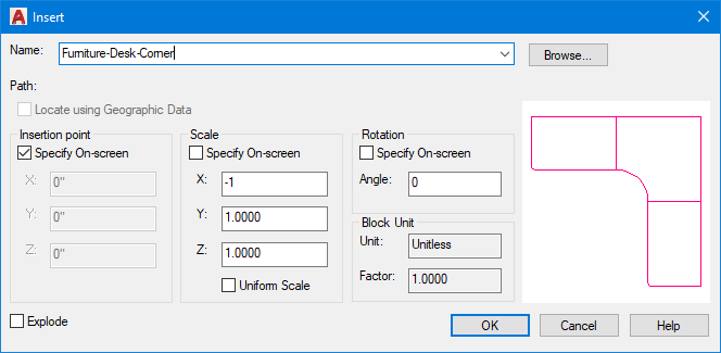
From the Name dropdown menu, select Furniture-Desk-Chair. To correct the orientation for upper-left corner placement, we'll employ a scaling technique: under Scale, enter an X value of –1. This negative scaling value flips the desk along the X-axis without altering its size – a professional trick for quickly reorienting blocks without creating new variations. Click OK and place the desk in the upper-right corner of the studio as shown.
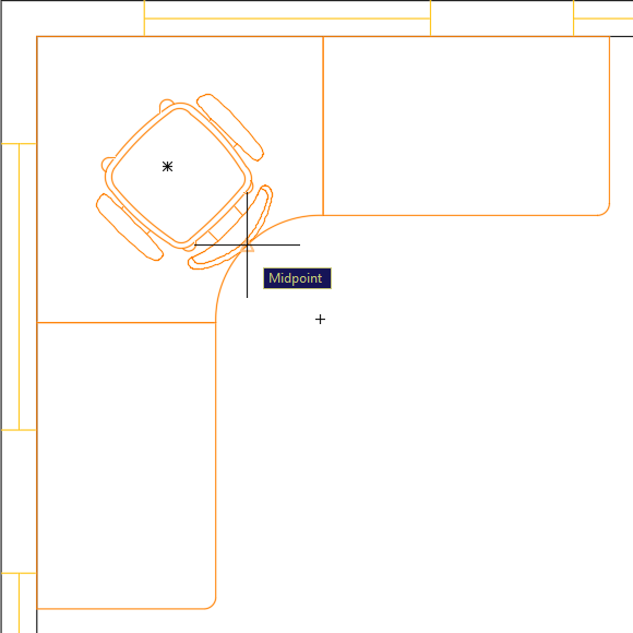
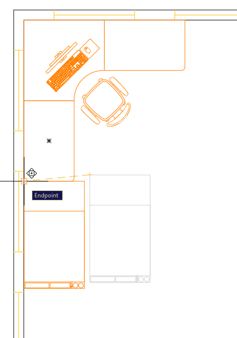
Keyboard shortcuts significantly accelerate workflow in professional environments. Demonstrate this by pressing I Enter (the Insert command alias) to quickly access the Insert dialog box. This method is particularly valuable during intensive drafting sessions. Select Furniture-Chair-Swivel from the Name list to add seating to your workspace.
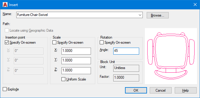
Strategic initial placement reduces subsequent modification work. Position the chair's base point at the midpoint of the desk's inner curved edge, as illustrated below. This seemingly simple step demonstrates professional foresight – by choosing a logical reference point, you'll simplify the centering process when using the Move tool in the next step.
Precision positioning requires careful attention to drawing aids. Ensure your Polar Angle is set to 45°, then activate the Move tool
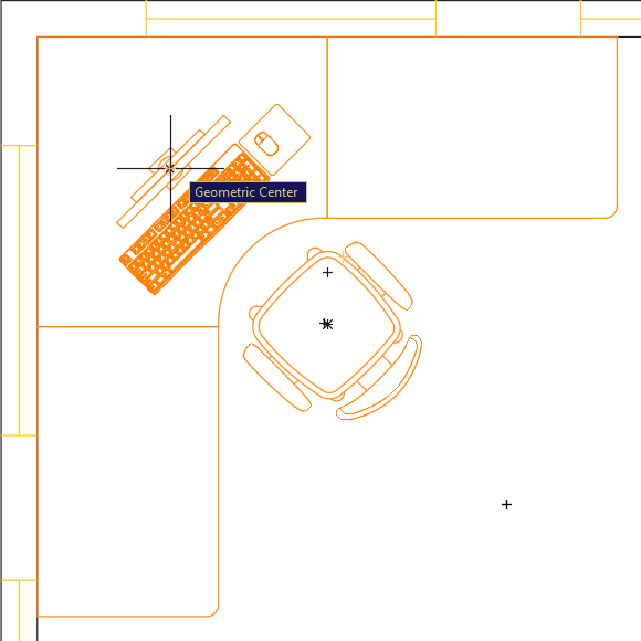
 and select the chair. For the base point, click the Geometric Center of the seat cushion. Move the chair along the 45° Polar Tracking line as shown below – this angular movement will perfectly center the chair with the desk, demonstrating how proper planning creates elegant solutions.
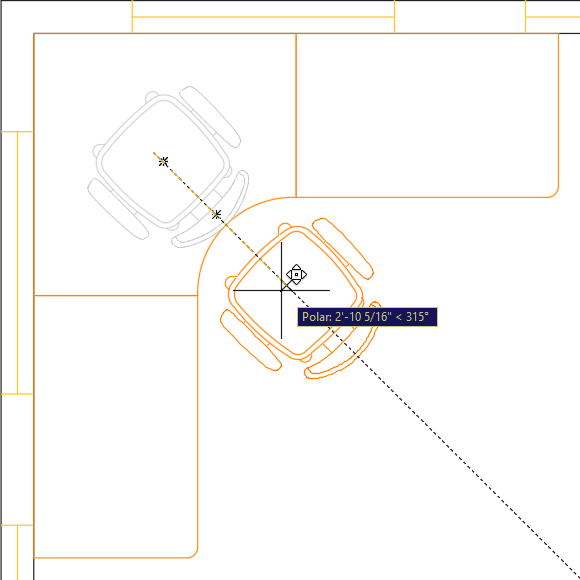
Mirroring is one of AutoCAD's most powerful productivity tools. Launch the Mirror command
 to create symmetrical copies of both the desk and chair for the studio's opposite side. Use the midpoint of the left wall as the first point of your horizontal mirror line, creating a balanced workspace layout with minimal effort.
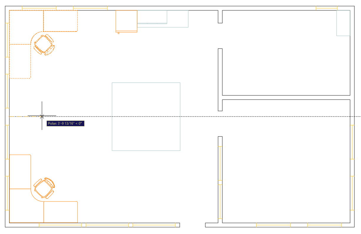
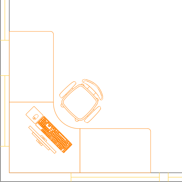
Now we'll add technology to our workspace. Execute the Insert command to place a PC block on the upper desk. Set the Rotation angle to 45° and position the base point at the desk's Geometric Center. This angled placement creates a more dynamic, realistic workspace arrangement than rigid orthogonal positioning.
Repeat the PC insertion process for the lower desk, but use a rotation angle of 135° to maintain visual balance. Note an important limitation: you cannot use the Mirror command to duplicate this PC because the block is asymmetrical – mirroring would create an unrealistic reversed orientation. This highlights why understanding your content is crucial for choosing the right duplication method.
This step demonstrates importing external drawing files as blocks – a fundamental skill for collaborative workflows. The drafting table isn't available in our current block list because it hasn't been inserted yet. Remember: blocks exist only within drawing files, so importing a block means selecting a .dwg file for insertion into your current drawing. Start the Insert command and click Browse in the Insert dialog box. Navigate to the Class Files folder, select Furniture-Drafting Table.dwg, and click Open. Set the Rotation angle to 180° and click OK. The base point may not align perfectly for immediate placement – this is common with externally sourced blocks. Position it approximately near the desk, then use the Move tool
to precisely place the base point at the drafting table's lower-left corner, positioning it adjacent to the desk as shown.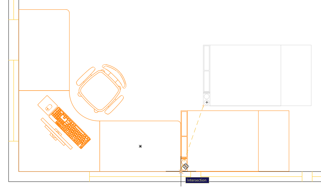
Apply the same process to place a second drafting table beside the other desk, using a 90° rotation angle as illustrated.
Professional Tip: This two-step approach – initial placement with Insert followed by precise positioning with Move – is standard practice in professional environments. Attempting to achieve perfect placement during initial insertion often wastes time, while this method combines speed with accuracy.
This next step illustrates a critical issue in block preparation. Press I Enter to start the Insert command and click Browse. Select Furniture-Desk.dwg from the Class Files folder and click Open. In the Insert dialog box, click OK. Notice two problems: the desk appears far from its base point, making placement difficult, and it displays in white (or black with light backgrounds) rather than matching the current A-Furniture layer color. These issues stem from improper block preparation – a common problem when working with externally sourced content. Press Escape to exit the Insert command and delete the desk if accidentally placed.
Now you'll learn proper block preparation – an essential skill for creating professional-quality content. Open the file Furniture-Desk.dwg. The base point problem occurs because when inserting .dwg files as blocks, AutoCAD uses the Origin Point (0,0) as the base point. The desk's current position places this origin far from the object. We need to reposition the desk so that 0,0 aligns with our desired base point. Press M Enter to start the Move tool
. Select the desk and click its Geometric Center as the base point. When prompted for the second point, press # (Shift–3) – this temporarily switches to Absolute coordinate mode. Type 0,0 and press Enter. This moves the desk's center to the origin point, ensuring the block's base point will be centered on the desk upon insertion.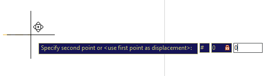
The color issue reveals a fundamental principle of AutoCAD layer management. When block objects reside on layers other than layer 0, they retain those layer properties regardless of where the block is placed. Currently, this desk sits on layer A-Walls (white), so the block appears white even when placed on the A-Furniture layer. However, objects on layer 0 become "Property by Layer," meaning they adopt the properties of whatever layer the block is inserted onto. Select the desk and change its layer to 0 to enable this behavior.
Technical Note: AutoCAD's color display system dates back to the software's origins when all computer screens were black. White objects were used for visibility against black backgrounds, but they print as black ink – which is why primary drawing layers typically use white. Modern AutoCAD allows customizable background colors through the Display tab in the Options dialog box (OP Enter), but the underlying color system remains unchanged for compatibility.
While color should typically be assigned by layer for clear layer identification, there are strategic exceptions. You may want certain block properties like linetype or lineweight to remain consistent regardless of the destination layer. Select the desk and open the Properties Panel (Ctrl–1). Change the Linetype to Continuous and the Lineweight to 0.30. This ensures consistent line appearance across all layers while allowing color to vary by layer – a professional approach to maintaining drawing standards. Save and close the Furniture-Desk.dwg file.
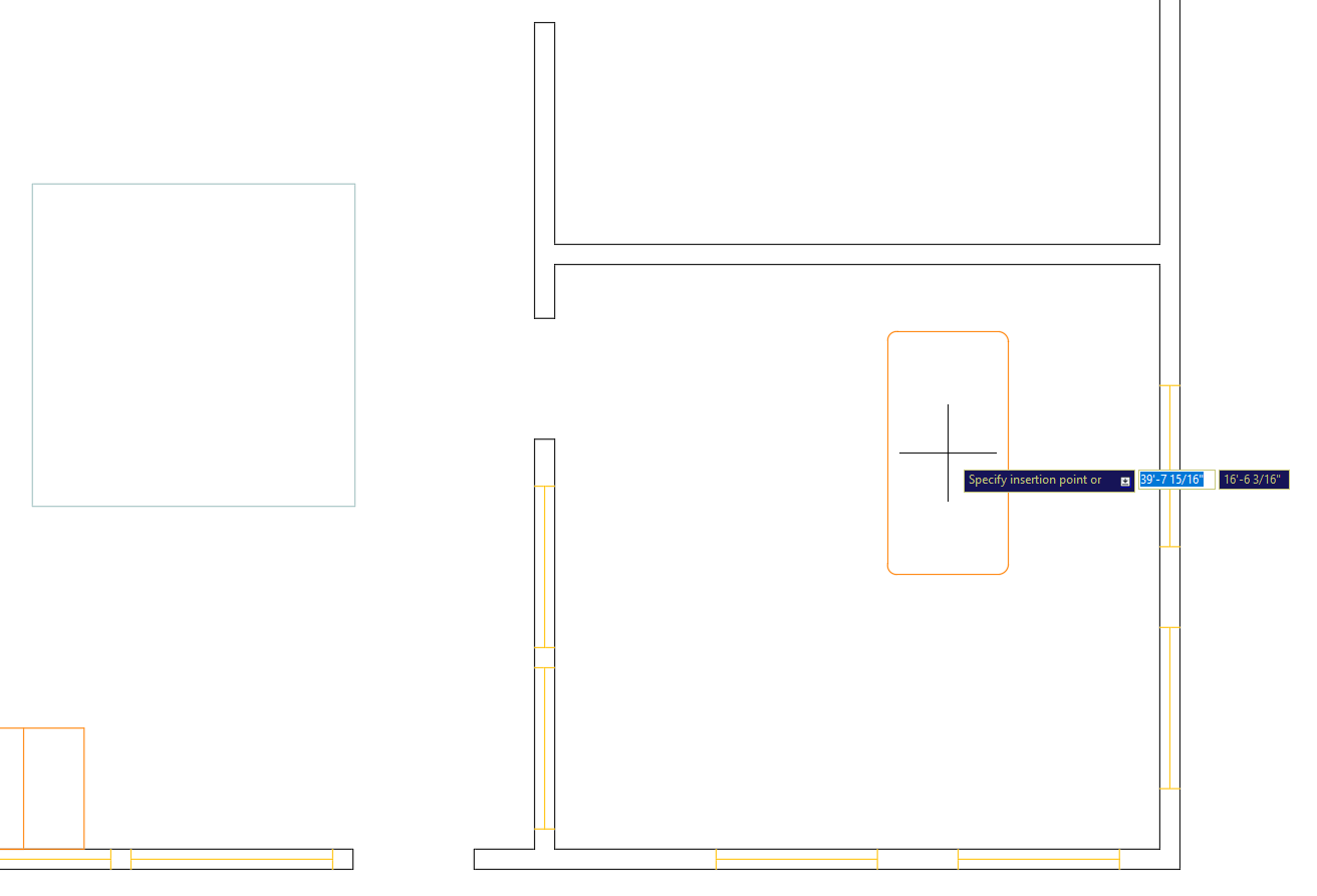
Return to Blocks-Studio.dwg and press I Enter to start the Insert command. Click Browse, select the corrected Furniture-Desk.dwg, and click Open. Since this file was previously inserted as a block, AutoCAD will prompt you to redefine the existing block. Click Redefine to update the block definition with your corrections – this demonstrates AutoCAD's intelligent block management system. In the Insert dialog box, enter 90° for the Rotation angle and click OK. Notice the immediate improvements: the base point now centers on the desk for easy placement, and the color matches the A-Furniture layer. Position the desk in the lower-right room (the office space) at the upper-right corner as shown below.
Understanding base points is crucial for accurate placement. The refrigerator block's base point is in the upper-right corner, which determines how it positions relative to your cursor during insertion.
Block Insertion Methods Comparison
| Feature | Dropdown Menu | Insert Dialog | Keyboard Command |
|---|---|---|---|
| Access Speed | Fast | Moderate | Fastest |
| Configuration Options | Limited | Full Control | Full Control |
| Scale Modification | No | Yes | Yes |
| Rotation Control | No | Yes | Yes |
Setting X scale to -1 flips the block horizontally without changing its size. This technique is essential for orienting furniture blocks to fit different room corners and layouts.
Block Positioning Best Practices
Provides most control for precise positioning and movement operations
Enables smooth repositioning along diagonal tracking lines
Place blocks approximately first, then fine-tune position with Move tool
Creates perfect symmetrical layouts across walls and centerlines
When blocks aren't in your current drawing's list, use the Browse button to import external DWG files. The file's origin point (0,0) becomes the block's base point automatically.
Objects on Layer 0 adopt the properties of their destination layer when inserted. Objects on other layers retain their original properties, which can cause color and formatting conflicts.
Property by Layer vs Property by Object
Setting Up Blocks for Optimal Insertion
Position Base Point at Origin
Move objects so the desired base point aligns with coordinate 0,0 using the Move command with absolute coordinates (#0,0).
Configure Layer Properties
Place block objects on Layer 0 for property inheritance, or assign specific properties for consistent appearance across layers.
Set Line Properties
Define specific linetypes and lineweights in Properties Panel when consistent appearance is required regardless of destination layer.
Test and Redefine
Insert the block, test positioning and appearance, then use the Redefine option to update the block definition with any corrections.