Topics Covered in This AutoCAD Tutorial:
Drawing Template Files (.dwt), Creating a File Based on a Template
Key Learning Areas
Drawing Template Files
Understanding .dwt files and their role in creating consistent drawing setups. Learn how templates preserve settings across projects.
Template-Based Creation
Step-by-step process for creating new drawings from existing templates. Master the workflow for efficient project initialization.
Exercise Preview
What You'll Accomplish
Experience the template-based workflow firsthand
Understand how templates preserve configurations
Apply real-world architectural drawing techniques
Exercise Overview
In this hands-on exercise, you'll create a professional drawing based on an architectural template while discovering how templates streamline your workflow. By the end, you'll understand how proper template usage can save hours of setup time on every project.
Drawing Template Files (.dwt)
Every successful AutoCAD project begins with the right foundation. When you create new drawing files (.dwg) ![]() using the New command (CTRL–N), AutoCAD requires you to select a Drawing Template file (.dwt)
using the New command (CTRL–N), AutoCAD requires you to select a Drawing Template file (.dwt) ![]() as your starting point. Think of templates as your project DNA—they contain all the essential settings that define how your drawing will behave.
as your starting point. Think of templates as your project DNA—they contain all the essential settings that define how your drawing will behave.
Templates store far more than basic settings. They preserve your custom units, scales, layer structures, text styles, dimension styles, attached blocks, and page layouts. Essentially, anything that can be saved in a drawing file ![]() can be embedded in a template file
can be embedded in a template file ![]() . This comprehensive approach means you can create specialized templates for different disciplines—architectural projects with imperial measurements, civil engineering drawings with survey coordinates, or mechanical designs using metric units.
. This comprehensive approach means you can create specialized templates for different disciplines—architectural projects with imperial measurements, civil engineering drawings with survey coordinates, or mechanical designs using metric units.
The genius of template files lies in their protective design. Once created, templates cannot be opened directly for editing, which means you'll never accidentally overwrite your carefully crafted template with project-specific content. This safeguard has saved countless professionals from losing weeks of setup work, making templates an essential part of any serious CAD workflow.
Template File Advantages
Consistency Across Projects
Templates ensure uniform settings, units, scales, layers, and styles across all new drawings. Eliminates repetitive setup work.
Protection from Overwriting
Template files cannot be accidentally saved over since they create separate .dwg files with different names and file types.
Specialized Configurations
Create different templates for architectural, civil, or mechanical drawings with appropriate units and measurement systems.
Anything that can be saved in a drawing file can be saved in a template file. This includes custom settings, units, scales, layers, styles, attached blocks, and layouts.
To Create a Drawing File from a Template
Select your desired template file
 using the New command (CTRL–N or File > New).
AutoCAD instantly generates a new Drawing file (.dwg)
 inheriting all the template's properties. The system automatically assigns a generic name like Drawing1.dwg, with the number incrementing based on how many new drawings you've created in your current AutoCAD session.
This naming convention provides additional protection—since your new file carries a different name and file type than the original template, there's no risk of accidentally overwriting your template when you save your work. The file remains a .dwg
by default, preserving your template's integrity.
Template to Drawing Workflow
Access New Command
Use CTRL-N or File > New to open the template selection dialog
Select Template
Choose appropriate .dwt file for your project type
New Drawing Created
AutoCAD generates a .dwg file with sequential naming (Drawing1.dwg, etc.)
Save with Custom Name
File remains as .dwg type, protecting original template from overwriting
Creating a File Based on a Template
Now let's put theory into practice. This step-by-step process will demonstrate how templates transform your drawing environment instantly, setting you up for efficient, standards-compliant work.
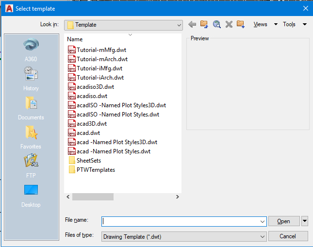
Launch the New command (File > New or CTRL–N) to open the Select Template dialog box. Notice the visual distinction: .dwt template files
display red icons, while .dwg drawing files show yellow and blue icons. This color coding helps prevent the common mistake of using File > Open when you meant File > New, or vice versa.By default, AutoCAD navigates to its built-in template library, but you'll often need custom templates stored elsewhere. For this exercise, navigate to your student file folder and select Architectural-Imperial.dwt. Double-click the template or click Open. AutoCAD immediately creates a new .dwg file with a name like Drawing1.dwg, ready for your architectural project.
Execute the Save As command (CTRL–Shift–S or File > Save As) and confirm the file type shows .dwg, not .dwt. Give your project a meaningful name: End Table.dwg, then click Save. This establishes your working file while keeping the original template untouched.
Access the Units command through the command line or Format menu to examine the template's unit configuration. The Drawing Units dialog box reveals the template's pre-configured settings.
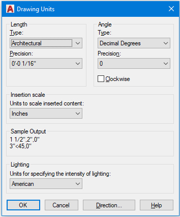
Observe how the template has automatically configured units for architectural work: inches as the base unit and Architectural length type. This means you'll enter measurements like 6 feet 5 inches as 6
'5, following standard architectural notation. Without this template, you'd need to configure these settings manually for every new project.Expand the Layer Control dropdown in the Layer panel or toolbar to reveal the template's organizational structure. The layer names immediately signal this template's architectural focus—you'll find layers for walls, doors, windows, and furniture rather than the mechanical components you'd see in manufacturing templates.
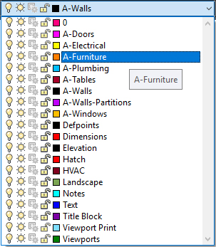
Each layer's color swatch indicates the display color for objects placed on that layer. This systematic approach to layer organization follows industry standards, ensuring your drawings remain compatible with other professionals' work and meet client expectations.
Select the A-Furniture layer to make it current. This action ensures that any new objects you create will automatically inherit this layer's properties, including color, linetype, and lineweight. Since you're drawing an end table, the A-Furniture layer is the logical choice, maintaining proper drawing organization from the start.
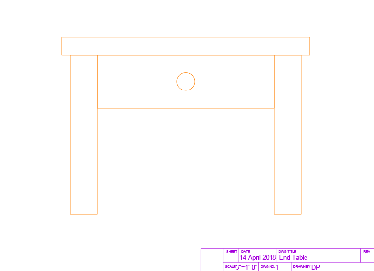
Study the dimensioned diagram below, which shows the end table you'll create. Notice how the dimensions follow architectural conventions, demonstrating real-world application of the template's settings.
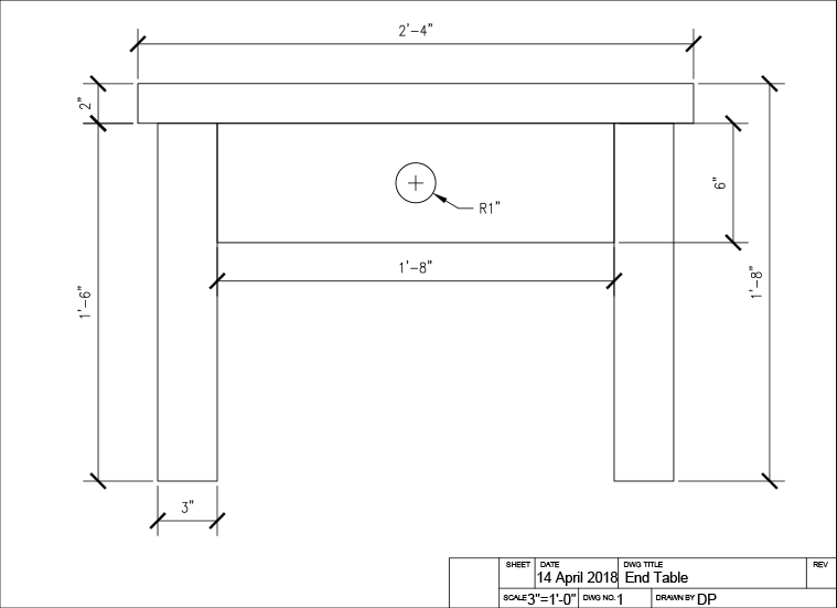
Activate the Rectangle command
 to create the table top. Click anywhere to establish your starting point, then input 2'''4,2 for the X and Y dimensions. Notice how the template's unit settings allow you to enter measurements in natural architectural format.
Press Enter to restart the Rectangle command
for the drawer component. Place your cursor at any starting location and enter 1'''8,6 for the drawer dimensions. The template ensures consistent formatting and accuracy across all elements.Create the table legs by drawing another rectangle with dimensions 3
"x1'8 at any convenient location. Use the Copy command to duplicate this leg, creating the second support. This workflow demonstrates how templates support efficient modeling practices.Employ the Move command
 to assemble your table components. Position the table top, drawer, and legs according to the reference image below, creating a cohesive furniture piece.
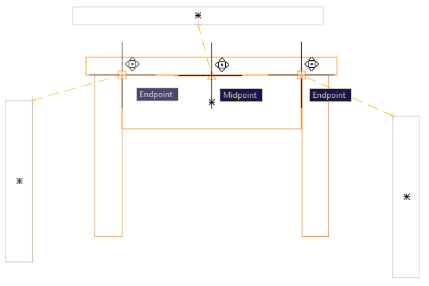
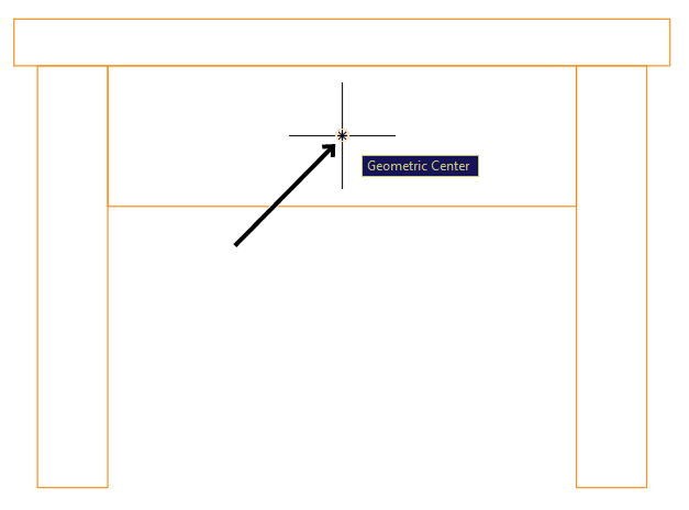
Complete your end table with the Circle tool
 to add the drawer knob. Use the Geometric Center object snap to precisely center the circle on the drawer rectangle—remember to hover your cursor over the rectangle's edge to reveal its geometric center point. Specify a radius of 1 inch for appropriate scale.
Professional Tip: Accurate snap placement is crucial for professional-quality drawings. The geometric center snap ensures perfect alignment, as shown below:
Congratulations—your end table is complete! Save and close the file. You've successfully leveraged a professional template to create a properly organized, standards-compliant drawing in a fraction of the time it would take starting from scratch.
File Type Recognition
| Feature | Template Files (.dwt) | Drawing Files (.dwg) |
|---|---|---|
| Icon Color | Red icons | Yellow and blue icons |
| Purpose | Create new drawings | Working documents |
| Accessibility | Cannot open directly | Can open and edit |
Architectural Drawing Setup Process
Template Selection
Navigate to Template Architectural-Imperial.dwt and double-click or use Open button
Verify Units Configuration
Check Drawing Units dialog shows Architectural type with feet/inches format (6'5 notation)
Review Layer Structure
Examine Layer Control for architectural-specific layers like walls, doors, windows, and furniture
Set Active Layer
Select A-Furniture layer for drawing furniture objects with appropriate properties
Layer names in architectural templates reflect drawing content types. This organization system helps maintain drawing standards and makes collaboration more efficient.