Topics Covered in This AutoCAD Tutorial:
Layer States, Layer Properties
Learning Objectives Checklist
Essential for managing complex drawings and preventing accidental modifications
Ensures consistent drafting standards and professional appearance
Temporary elements that aid in precision without cluttering final drawings
Improves system performance while maintaining drawing organization
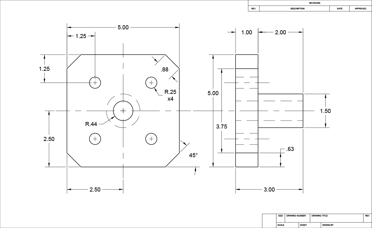
Exercise Preview
Exercise Overview
Mastering layer management is fundamental to professional CAD drafting efficiency. In this comprehensive exercise, you'll develop essential skills for controlling layer visibility and properties by manipulating Layer States. You'll also learn the critical technique of assigning linetypes to objects through strategic layer placement—a workflow that ensures consistency across complex technical drawings and maintains industry standards for mechanical drafting.
This exercise uses Layers-Mechanical.dwg, which is based on a Mechanical template with pre-configured layers appropriate for mechanical drafting standards.
Layer Management Workflow
Identify Current Layer
Check the Layer Control to see the active Object layer and understand layer assignments of existing elements
Use Make Current Command
Select LAYMCUR or Make Objects Layer Current tool to quickly switch active layers based on selected objects
Draw with Layer-Specific Properties
Create new objects that inherit the linetype and properties of the current active layer
Manage Layer Visibility
Freeze construction layers to declutter the drawing while preserving objects for potential future use
Step-by-Step Instructions
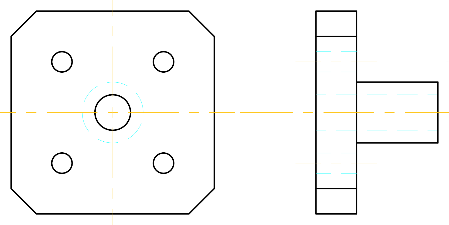
Open the file Layers-Mechanical.dwg. This drawing file leverages a mechanical template with industry-standard layers specifically configured for mechanical drafting workflows. These pre-configured layers follow established conventions that ensure your drawings meet professional standards and integrate seamlessly with manufacturing processes.
The current layer, as indicated in the Layer Control, is the Object layer. Select one of the gray dashed lines to observe how AutoCAD's layer system works. The Layer Control will automatically update to show that this element resides on the Construction layer. Construction layers serve as digital scaffolding—they contain guidelines that help align objects during the drafting process but are typically hidden or removed from final deliverables to maintain drawing clarity. Press Escape to deselect the object. Notice how the Layer Control reverts to displaying the Object layer, confirming it remains the active working layer.
Now you'll create hidden lines to represent the center hole's edges in the side view—a standard practice in technical drawing. While you learned to change layers via the Layer Control in previous exercises, AutoCAD offers a more efficient method when working with existing geometry. Use the Make Current command (LAYMCUR, or the Make Objects Layer Current tool in the layer toolbar) for streamlined workflow. Click the Make Current button to activate the command. When prompted by the Command Line, click one of the cyan dashed hidden lines that indicate holes in the side view. Since these lines reside on the Hidden layer, the Make Current command automatically switches your working environment to the Hidden layer, ensuring all new geometry inherits the appropriate hidden line properties.
The existing construction lines provide perfect alignment references for the center hole's top and bottom edges—this demonstrates how proper layer organization facilitates precision drafting. Press L Enter to initiate the Line Command. Use endpoint snapping to precisely locate the construction line intersection at the top of the center hole where it meets the side view's left edge. Click to establish the line's starting point, then drag horizontally along the tracking line to the side view's leftmost boundary. Employ intersection snapping to complete the line with precision. Double-tap the Spacebar to terminate and restart the Line command, then create the bottom hidden edge using the identical methodology you applied to the top edge.

With the hidden details complete, you'll now focus on the object's primary geometry. Activate the Make Current command and select any solid black line to designate Object as your active layer. This layer switch ensures your subsequent linework will display with the appropriate solid linetype and weight for visible edges.
Use the Line tool
 to complete the side view's outer edges, specifically the 45° chamfered cuts. Leverage Object Snap functionality to precisely position line endpoints where construction lines intersect the side view geometry. Since Object is now your current layer, all new linework will automatically display as solid black lines with appropriate lineweight—maintaining the visual hierarchy essential for technical communication.
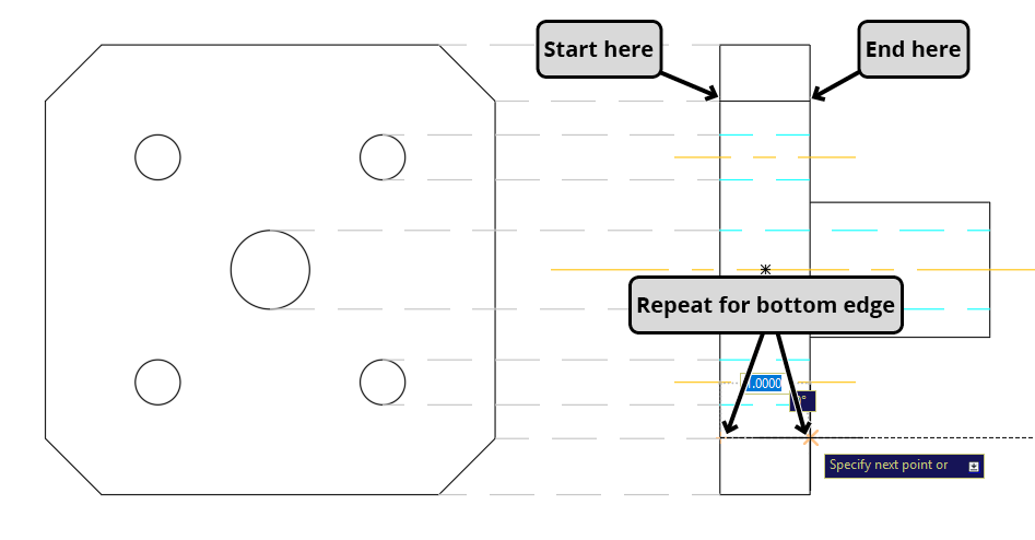
Having completed the primary geometry, the Construction layer elements have served their purpose and should be removed from the active workspace. Rather than deleting these potentially useful reference elements, you'll employ the Freeze function—a professional best practice that preserves construction geometry while optimizing display performance. When you Freeze a layer, AutoCAD removes its objects from both the visual display and memory allocation, significantly improving system performance with complex drawings. Expand the Layer Control to access layer properties. The Sun icons indicate Thawed (visible) layers. Click the Sun icon
 adjacent to the Construction layer. The icon transforms into a Snowflake
  , confirming the layer is frozen and its contents are now invisible and unloaded from system memory.
With construction clutter eliminated, your workspace is now optimized for precision work. Next, you'll create centerlines for the front view—critical elements for communicating rotational symmetry and machining references. Use the Make Current tool to designate Center as your active layer by clicking any existing centerline in the side view. This ensures your new centerlines inherit the proper linetype and properties. Create a horizontal 6-inch centerline positioned above the object geometry. Select the completed centerline and click its middle grip to activate move mode. Precisely relocate the centerline so it passes through the center point of the middle circle in the front view, using the Center object snap for accuracy as demonstrated in the illustration below.

While maintaining centerline selection, type RO Enter to activate the Rotate command
 . Establish the base point at the line's midpoint for proper rotational control. Press C Enter to access the Copy option within the Rotate command—this powerful feature allows simultaneous rotation and duplication, streamlining your workflow. Align the rotated copy with the vertical tracking line and click to create a perfect 90° rotation, establishing both horizontal and vertical centerline references.
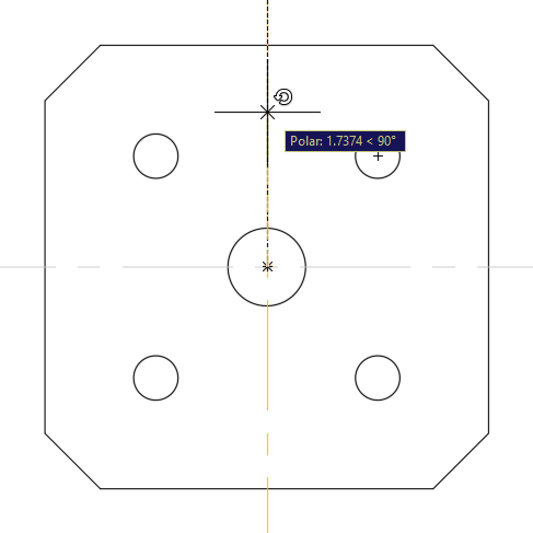
Switch to the Hidden layer as your current working layer to maintain proper linetype assignments. Initiate the Circle command
 and position the new circle's center point to coincide precisely with the middle circle's center in the front view. This creates the hidden representation of the center hole as viewed from the front.
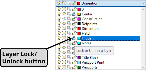
Professional workflows require safeguarding completed elements from accidental modification. Layer locking provides this protection while maintaining visibility for reference purposes. Expand the Layer Control to reveal the Lock icons, which appear as open padlocks for each layer. Click the Lock icons for both the Center and Hidden layers. Observe how objects on locked layers become visually subdued through fading, providing clear feedback about their protected status. When you attempt to select objects on locked layers, AutoCAD will highlight them to indicate layer assignment, but no grips appear and no modifications are possible—ensuring your carefully crafted geometry remains intact during subsequent editing operations.
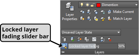
Fine-tune your visual workspace by expanding the Layers Panel to access the Locked Layer Fading slider control. This feature allows precise adjustment of how prominently locked layers appear in your drawing environment. Adjust the slider or double-click the percentage value to input a specific number—higher percentages increase fading intensity, helping distinguish active geometry from protected reference elements. This visual control helps maintain focus on editable elements while preserving important contextual information.
Activate lineweight visibility in the Status Bar to visualize the hierarchical line thickness system that's fundamental to technical drawing standards. This feature reveals how different layers employ varying lineweights to communicate geometric relationships and drawing conventions—a critical aspect of professional mechanical drafting that ensures drawings meet industry standards for manufacturing and quality control.
Complete your exercise by clicking the C-Size Layout tab to view your drawing in a professional presentation format. Thaw the Dimensions layer to reveal the completed dimensioning scheme. Pay particular attention to how these mechanical dimensions differ significantly from the architectural dimensions you encountered in previous exercises. This drawing utilizes the Mechanical-Imperial.dwt template, which applies industry-specific dimensioning styles, text formatting, and tolerance conventions that align with manufacturing standards—demonstrating how template selection fundamentally influences drawing presentation and professional compliance.
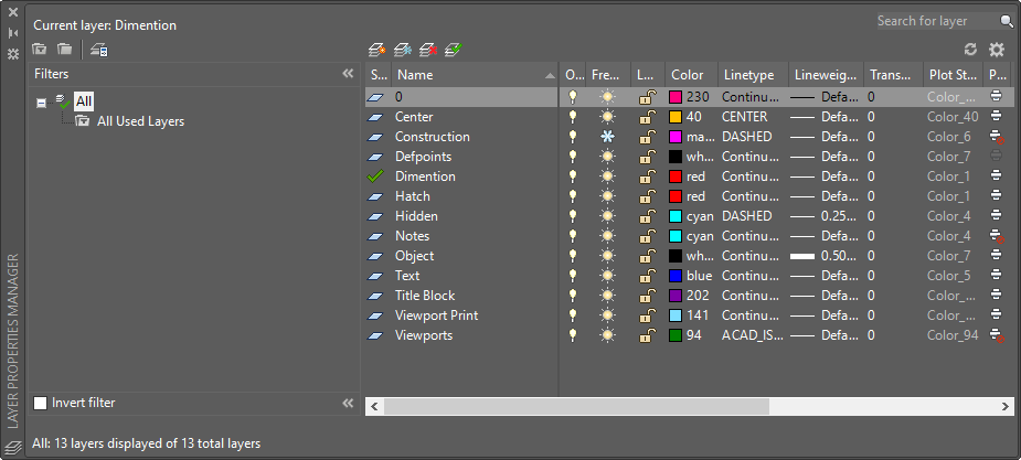
The Layer Properties Manager
Advanced layer control is accomplished through the Layer Properties Manager—a comprehensive interface that will be explored extensively in Level 2 coursework. Access this powerful tool by entering the LAYER command or clicking the Layer Properties button  . This centralized control panel manages all layer attributes including color, linetype, lineweight, and plot settings. As demonstrated throughout this exercise, layer properties are typically preconfigured in template files, establishing consistent standards across projects and ensuring compliance with industry drafting conventions. Understanding the Layer Properties Manager becomes increasingly critical as you advance to complex multi-discipline projects where layer coordination and standards management are essential for team collaboration and project success.
Layer State Controls
Freeze vs Hide
Frozen layers are not rendered by the computer, improving performance. Thawed layers show Sun icons, while frozen layers display Snowflake icons.
Layer Locking
Locked layers prevent accidental modification. Objects fade based on the Locked Layer Fading slider, and grips are disabled for locked objects.
Template Integration
Layer properties are typically pre-assigned in template files. Mechanical templates use different dimensioning styles than architectural templates.
Layer Properties Manager Access
Command Entry
Type LAYER command in the command line to open the Layer Properties Manager dialog
Toolbar Access
Click the Layer Properties button in the layer toolbar for quick access to management tools
Template Configuration
Layer properties are pre-configured in template files like Mechanical-Imperial.dwt for consistent standards
Freezing unused layers instead of just hiding them reduces memory usage and improves AutoCAD performance, especially important for large or complex drawings.