Topics Covered in This AutoCAD Tutorial:
Master professional mechanical drawing workflows by leveraging template-based design and exploring the comprehensive settings that streamline your drafting process.
Tutorial Learning Path
Template Setup
Learn to access and apply mechanical drawing templates using the QNew button and template assignment methods
Settings Exploration
Examine pre-configured units, layers, and drawing properties that come standard with mechanical templates
Practical Application
Create a mechanical hub drawing using template-specific tools and layer conventions
Exercise Preview
This hands-on exercise demonstrates how mechanical templates save time and ensure consistency by providing pre-configured drawing environments tailored for technical documentation.
Drawing Components Created
Exercise Overview
In this comprehensive exercise, you'll harness the power of AutoCAD's mechanical templates to create precise technical drawings. You'll discover how industry-standard templates accelerate your workflow while ensuring consistency across projects. By the end of this tutorial, you'll understand how to leverage pre-configured settings, layer conventions, and drawing standards that professional mechanical drafters rely on daily.
Pre-Exercise Requirements
Ensure template file is accessible in student folder or assigned to QNew button
Required for accurate angular construction of hub geometry
Mechanical layers use line type names rather than object descriptions
Using a Mechanical Drawing Template
Templates form the foundation of efficient CAD work, embedding decades of industry best practices into your starting point. Let's explore how to maximize their potential in your mechanical design workflow.
Access the QNew button
 in the Quick Access Toolbar or execute QNEW Enter. Since you previously assigned the Mechanical-Inches.dwt template file to the QNew button in the last exercise, AutoCAD will automatically generate a new drawing file based on Mechanical-Imperial.dwt. This template contains pre-configured layers, line types, and dimension styles that align with ASME Y14.5 standards. If no template was assigned to QNew, the Select Template dialog will appear—simply navigate to your student folder and select Mechanical-Inches.dwt. Reference the previous exercise if you need to reassign a template to QNew for streamlined access.
Initiate the Save As command using CTRL–Shift–S or navigate to File > Save As. Notice that AutoCAD automatically converts the file type from .dwt (template) to .dwg (drawing), creating a working file while preserving your original template. Name the file Hub and save it to your student folder. This naming convention reflects the mechanical component you'll be designing—a hub assembly commonly found in rotating machinery.
Launch the Units command or select Units from the Format menu to access the Drawing Units dialog box, shown below. Understanding unit configuration is crucial for precision manufacturing documentation.
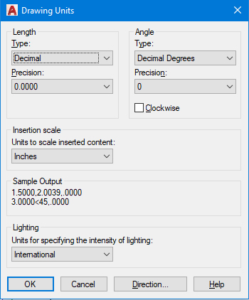
Observe that the units are configured for inches with Decimal length type—the standard for American mechanical engineering. This configuration allows you to input measurements as decimal values (e.g., 2.5 for two and one-half inches), matching typical machining tolerances and manufacturing specifications. This precision is essential for components that must interface with other mechanical parts.
Expand the Layer Control panel as illustrated below. In mechanical drafting, layer naming follows object line conventions rather than architectural object types, reflecting the visual hierarchy of technical drawings.
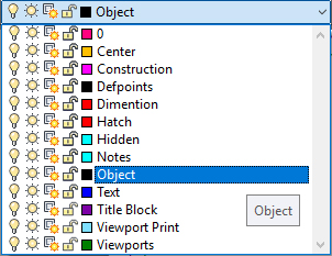
Note that the Current Layer is set to Objects, inheriting this setting from the Mechanical-Inches.dwt template. This layer uses continuous lines for visible edges and surfaces. All new geometry will automatically adopt the properties assigned to the Objects layer, including line weight and color coding that comply with drafting standards. Maintain the Objects layer as current for the visible geometry you'll create next.
You'll now construct a mechanical component following the dimensioned drawing below. Pay attention to the decimal units and the mechanical dimensioning style, which follows industry standards for manufacturing drawings.
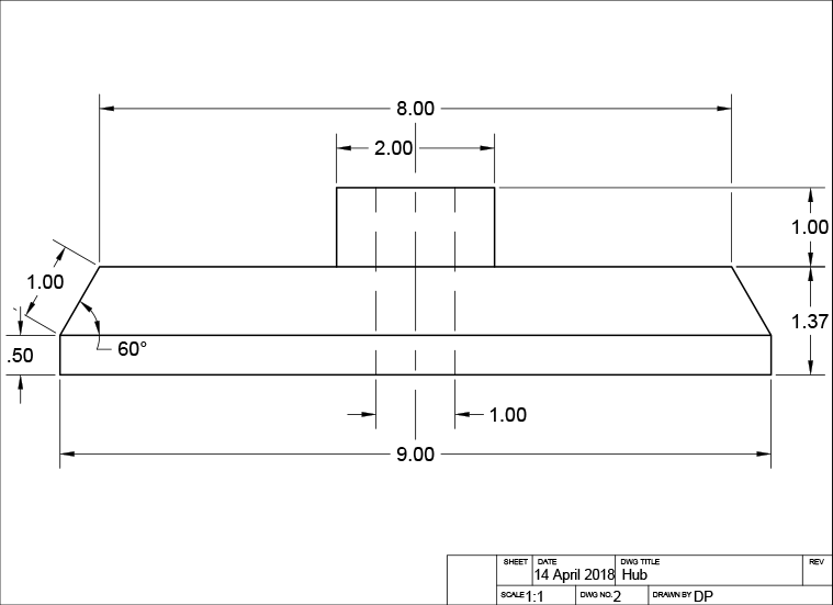
Execute the Rectangle command
 to create the hub's base profile. Click anywhere in the drawing area to establish the rectangle's start point, then input 9,.5 to define the X and Y dimensions. This creates a 9-inch wide by 0.5-inch tall base—typical proportions for a mechanical hub that balances strength with material efficiency.
Ensure Polar Tracking is activated and configure the incremental angle to 30°. This setting enables precise angular construction for the angled surfaces common in mechanical components, allowing for easy snap-to angles that align with standard machining practices.
Activate the Line tool
 . Snap to the upper-left corner of the rectangle to establish your starting point. Draw the first line segment 1 inch at 60° as shown, creating the angled transition typical in machined components to reduce stress concentration. Pull horizontally to the right, snap to the horizontal tracking line, and input 8 for the distance. Complete the profile by snapping to the endpoint at the upper-right corner of the rectangle. Press Enter twice to end and restart the Line tool for the next sequence.
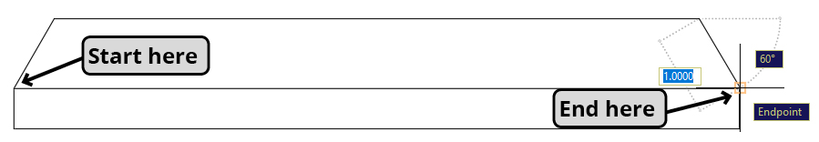
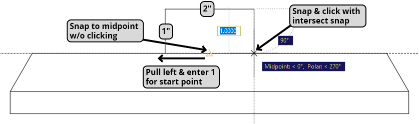
Without clicking, snap to the midpoint of the topmost line segment and pull left along the horizontal tracking line. Input 1 to position the starting point 1 inch left of the midpoint. Pull upward along the vertical tracking line, enter 1, and press Enter to create the first vertical segment. Pull right along the horizontal tracking line and input 2 for the next segment. Pull down using the 90° tracking line and employ the Intersect snap to connect precisely to the hub's top surface. Press Enter to complete the line command. This creates the raised boss feature common in mechanical hubs for mounting hardware.
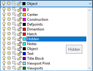
In the Layer Control, select the Hidden layer to make it current. The Hidden layer utilizes dashed line types to represent edges that would be obscured from view at the current viewing angle—a critical convention in orthographic projection that communicates 3D form in 2D drawings.
Press L Enter to initiate the Line command
. Snap to the midpoint of the topmost line segment, pull left along the horizontal tracking line, and input .5 to establish the hidden line's starting point. Pull downward along the vertical tracking line, input 1, and press Enter for the first segment. Continue pulling down on the 90° tracking line and use the Intersect snap to connect the endpoint precisely to the hub's bottom edge. This hidden line represents the internal geometry of the raised feature.Press CO Enter to start the Copy command
 . Select the hidden line you just created and click any snap point on the line to establish the base point. Pull right along the horizontal tracking line and input 1 to place a copy one inch to the right. This creates symmetrical hidden edges, maintaining the visual balance essential in technical drawings.
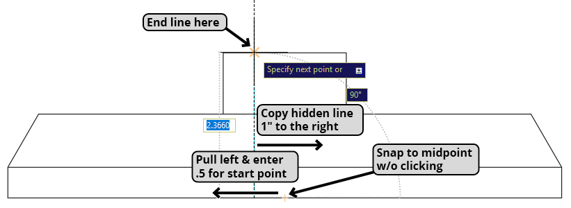
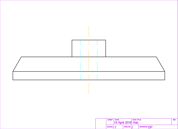
Create a vertical centerline 4 inches long at any convenient location. Centerlines are crucial reference elements in mechanical drawings, indicating axes of symmetry and machining centers.
Execute the Move command
 and select the centerline you just created. For the base point, click the centerline's midpoint to ensure precise positioning. Snap to the midpoint of the second-highest horizontal line as illustrated below. This positions the centerline to indicate the hub's axis of rotation—critical information for manufacturing and assembly.
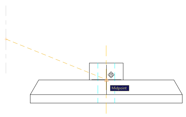
Save and close the file to preserve your work. You've successfully created a mechanical component drawing using professional template conventions, demonstrating how proper layer management and drafting standards contribute to clear, manufacturable technical documentation.
Template Activation Process
Access Template
Press QNew button or use QNEW command to create new drawing from assigned mechanical template
Verify Settings
Check Units dialog to confirm decimal inches and examine layer structure for mechanical conventions
Save as Drawing
Use Save As command to convert template (.dwt) to drawing file (.dwg) with appropriate naming
Objects layer serves as the default for visible edges, while Hidden layer uses dashed line type for non-visible edges. This follows standard mechanical drawing conventions.
Drawing Construction Techniques
Geometric Foundation
Start with base rectangle using decimal dimensions. The 9 x 0.5 inch base provides the foundation for the mechanical hub component.
Tracking and Snapping
Use polar tracking at 60-degree angles and endpoint snapping for precise construction. Horizontal and vertical tracking lines ensure accuracy.
Layer-Specific Elements
Switch to Hidden layer for non-visible edges and use Copy command for duplicate hidden lines. Maintain proper line type conventions throughout.