Topics Covered in This Cinema 4D Tutorial:
Sweep Generator, Shapes & Lines
Exercise Preview

Exercise Overview
In this comprehensive exercise, you'll master the art of creating and animating a sweep to produce compelling write-on text effects. This technique combines Cinema 4D's powerful spline modeling capabilities with animation fundamentals, enabling you to craft professional-quality text reveals that rival traditional After Effects approaches while leveraging true 3D dimensionality.
Previewing the Final Video
Let's examine the final result you'll be creating. If you're currently in After Effects, keep it open but switch to your Desktop to maintain your workflow continuity.
On the Desktop, navigate to Class Files > C4D in AE Class > Spline Modeling—Sweep > Preview Movie and double–click Love Script.mp4.
Analyze the following key elements:
- The text gracefully writes onto the screen in a sophisticated 3D interpretation of the classic write–on effect that After Effects is renowned for. Notice how the dimensional quality adds depth and visual interest that flat 2D approaches simply cannot achieve.
Replay the video multiple times to study the timing and flow, then close it when you've absorbed the technique.
Understanding this preview establishes your creative target and helps you visualize the technical concepts we'll explore throughout this exercise.
Getting Started
Launch Cinema 4D Lite and prepare your workspace for optimal productivity.
If you're opening the application fresh, dismiss the Quick Start Dialog to access the main interface.
In C4D Lite, if you have an existing project open, choose File > Save to preserve your current work.
Choose File > Close All Projects to establish a clean working environment.
Choose File > Open Project.
- Navigate to C4D in AE Class > Spline Modeling—Loft
- Double–click on Love Script—Started.c4d to open the starter file.
Choose File > Save Project As to create your working version
Navigate to C4D in AE Class > Spline Modeling—Sweep
Name the file Your Name—Love Script.c4d using your actual name for easy identification
Press Save. Your project environment is now properly configured for the exercise ahead.
This methodical setup ensures you maintain organized project files while protecting your progress throughout the modeling process.
What is a Sweep?
In professional 3D modeling workflows, the term "Sweep" refers to a fundamental yet powerful modeling technique that generates complex 3D geometry by extruding a 2D cross-sectional shape along a defined path. This methodology proves invaluable for creating organic forms, architectural elements, and stylized text effects. The Sweep generator in Cinema 4D empowers you to construct an extensive range of objects—from basic tubes and cylinders to sophisticated architectural moldings, decorative bottles, intricate vases, and comprehensive pipe systems used in industrial visualization.
The sweep workflow operates on a straightforward principle: you define a 2D profile (the cross-sectional shape) and a path spline (which determines the trajectory and direction of the extrusion). The Sweep generator then intelligently constructs 3D geometry by moving your profile along the path while maintaining proper surface normals and topology. Advanced attributes within the generator provide granular control over orientation, scaling, rotation, and segmentation—allowing for precise customization that meets professional production standards in 2026's competitive 3D marketplace.
The Sweep generator creates 3D objects by stretching a 2D shape along a path. This technique enables creation of complex forms from simple tubes to intricate pipe systems and organic shapes.
Creating a Modeling Template
Professional 3D artists consistently rely on reference materials to ensure accuracy and maintain creative vision throughout the modeling process. To optimize your learning experience, we've pre-configured a reference template that streamlines your workflow while teaching industry-standard practices. This template consists of a carefully positioned plane with an applied image texture, creating an ideal backdrop for precise modeling work.
When approaching client projects or personal work, establishing clear visual references dramatically improves modeling efficiency and final output quality. The technique of applying reference imagery to geometric planes and integrating them into your 3D scene represents a cornerstone methodology used across animation studios, architectural visualization firms, and product design agencies worldwide.
If circumstances require you to recreate this reference system independently, follow these professional-grade steps:
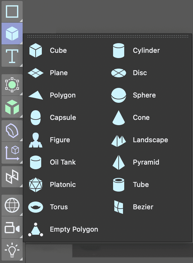
In the Create Menu press and hold the Cube button to reveal Cinema 4D's full array of primitive shapes.
Select the Plane object from the expanded primitive menu.
In the Perspective viewport, click the Toggle Active View
 button to reveal all four orthographic viewports for comprehensive scene navigation.
In the Object Manager, double–click the Plane and rename it Model Reference or another descriptive identifier that facilitates quick object location during complex scene management.
Rotate the plane using the rotation handles until it faces toward your primary modeling viewpoint in the Front view.
In the Attribute Manager, click the Object tab and modify the plane's width and height dimensions to precisely match your reference image's aspect ratio.
NOTE: Since Cinema 4D's default material projection behavior stretches textures to fit object bounds, matching your plane dimensions to your reference image dimensions prevents unwanted distortion that could compromise modeling accuracy.
Click within the Front view and press H or choose View > Frame Geometry to automatically frame your reference plane optimally.
- Repeat this framing operation for the remaining viewports to maintain consistent visual reference across all angles.
In the Front viewport, choose Display > Gouraud Shading. This shading mode enables real-time texture visibility within the viewport once you apply your reference material.
Click the Material Manager
 button to access Cinema 4D's comprehensive material creation and management system.
Click the New Default Material
 button to generate a fresh material for your reference system.
Double–click the new material's default name and rename it Model Reference for clear identification within your material library.
- Press Return (Mac) or Enter (Windows), or click any empty space to confirm the name change.
Double–click the material's spherical icon
 to launch the comprehensive Material Editor interface.
In the Material Editor, disable the Reflectance channel by toggling its activation switch. Reflective reference materials create visual distractions that interfere with accurate modeling work.
Click the Color channel to ensure it's actively selected and ready for image input.
Click the dropdown arrow adjacent to the texture field and choose Load Image from the expanded menu.
Navigate to your chosen reference image file and double–click to load it into the material system.
NOTE: If your reference image resides outside your current C4D project's root directory, the application intelligently offers to copy the image file locally. This practice prevents asset linking issues that could disrupt rendering workflows or cause problems when transferring projects between systems.
Close the Material Editor to return to the main interface.
Drag your newly created material from the Material Manager directly onto the Model Reference plane within the Object Manager hierarchy.
NOTE: Alternative application methods include dragging materials directly onto 3D objects within any viewport, providing flexible workflow options that accommodate different working preferences.
Close the Material Manager to declutter your interface and focus on modeling tasks.
In the Object Manager, click the Model Reference object to select it and access its transformation controls.
Utilize the Move tool to position your reference plane behind the world origin point. This strategic placement ensures clear visibility of your created geometry without unwanted intersection artifacts.
For optimal project organization—a critical aspect of professional 3D workflows—we'll isolate the reference image on a dedicated layer.
- In the Object Manager, CTRL–click (Mac) or Right–click (Windows) on the Model Reference object to access the contextual menu.
- Choose Add to New Layer. Notice the layer indicator adjacent to your object's name becomes highlighted, confirming successful layer assignment.
Locate the Layer Manager panel, labeled Layers within your interface layout.
- Double–click the newly created layer and rename it Reference for immediate identification.
- Click the lock icon positioned beneath the L column header to prevent accidental modifications to your reference setup.
NOTE: Each column header controls specific layer properties: S provides solo functionality, V manages visibility, and additional options are available through the Layer Manager's View menu system for comprehensive layer control customization.
Click the Attribute Manager tab to reveal layer-specific options and settings when a layer remains selected.
Press Cmd–S (Mac) or CTRL–S (Windows), or choose File > Save Project to preserve your reference setup progress.
With your modeling template properly configured, you've established a professional foundation that will guide accurate spline creation throughout the remaining exercise.
Reference Template Setup Process
Create Base Plane
Add a plane primitive and resize it to match your reference image dimensions to prevent texture distortion.
Apply Reference Material
Create a new material, disable reflectance, load your reference image, and apply it to the plane object.
Organize and Position
Place the reference on a locked layer and position it behind the origin for clear modeling workspace.
Drawing a Path for the Sweep with the Spline Pen
The foundation of any successful sweep operation lies in creating a well-crafted path spline that accurately defines your intended geometry flow. This path can be either open (with distinct start and end points) or closed (forming a complete loop), and can be constructed using any of Cinema 4D's sophisticated spline tools. For projects requiring complex, organic, and flowing shapes—such as the script lettering we're creating—the Spline Pen and Sketch tools provide the precision and intuitive control that professional artists demand.
Activate the Spline Pen
 tool from the tool palette positioned to the left of your viewport interface.
In the Front view, adjust your viewport framing until you achieve comfortable visibility of the reference image with adequate working space around its perimeter.
Begin creating your spline path by systematically placing points to establish the rough contour of your reference lettering. Focus initially on capturing the overall flow and proportions rather than minute details—refinement comes in subsequent steps.
Press the Esc key to finalize your spline creation and transition from point-placement mode to editing mode.
Press the Spacebar to automatically switch to your previously used Selection
 tool, enabling precise vertex manipulation.
Select vertices that require conversion from Hard Tangents (creating sharp corners) to Soft Tangents (producing smooth curves). This selection process directly impacts the organic quality of your final lettering.
CTRL–click (Mac) or Right–click (Windows) on your selected vertices and choose Soft Interpolation from the contextual menu to enable curved transitions.
Press E to activate the Move tool, providing access to both vertex positioning and tangent handle manipulation.
Carefully adjust the tangent handles extending from your converted vertices, sculpting smooth curves that closely match your reference lettering's character and style.
NOTE: The Move tool serves dual purposes in spline editing: repositioning vertices for structural adjustments and manipulating tangent handles for curvature refinement.
Continue iteratively refining vertices and tangent relationships until your spline path accurately represents the reference lettering with professional polish.
NOTE: To break tangent handle symmetry for asymmetric curve control, hold the Shift key while dragging individual handles. To remove unnecessary vertices that may be cluttering your spline, select them and press Delete (Mac) or Backspace (Windows).

- Press Cmd–S (Mac) or CTRL–S (Windows) or choose File > Save Project to preserve your spline creation progress.
Spline Creation Methods
The Sketch Tool
Cinema 4D incorporates an intuitive tool specifically engineered to replicate natural hand-drawing behavior: the Sketch tool. This innovative feature proves particularly valuable when creating organic, flowing splines that benefit from gestural input rather than precise point placement. Additionally, the Spline Smooth tool provides post-creation refinement capabilities, allowing you to soften overly complex or jagged paths into elegant, production-ready curves.
- To activate the Sketch tool, long–press on the spline pen icon until the tool group expands.
- To use the tool effectively, click and drag naturally within any viewport, allowing your hand movement to guide spline creation organically.
- If your sketched spline appears too rough or contains excessive detail, apply the Spline Smooth tool to intelligently reduce complexity while preserving overall character.
Your completed spline path now serves as the trajectory foundation for the sweep operation, defining precisely how your 3D lettering will flow through space.
Spline Tools Comparison
| Feature | Spline Pen | Sketch Tool |
|---|---|---|
| Input Method | Point and click | Natural drawing |
| Precision Level | High precision | Organic flow |
| Best Use Case | Geometric shapes | Hand-drawn styles |
| Post-Processing | Manual tangent adjustment | Spline Smooth tool |
Sweeping with a Shape
The second critical component of any sweep operation is the profile shape—the 2D cross-section that will be extruded along your carefully crafted path. This profile must be a closed spline to generate solid 3D geometry, and its dimensions directly influence the final appearance and character of your swept object.
In the Create menu, long–press on the Rectangle spline tool until the complete spline menu expands, revealing all available primitive spline options.
- Click on the Circle spline to create a perfect circular profile for your sweep operation.
NOTE: To convert your circular profile into an elliptical shape for varied proportions, activate the Ellipse switch within the Attribute Manager's Object properties.
In the Attribute Manager, precisely adjust the circle's radius attribute to achieve your desired cross-sectional thickness for the final lettering.
NOTE: When working with path splines that contain overlapping segments or tight curves, exercise caution with profile sizing to prevent unwanted geometry intersection that could compromise surface quality or create rendering artifacts.
In the Create panel, long–press on the Subdivision Surface generator until the generator menu expands, displaying all available procedural modeling options.
- Choose Sweep from the generator menu to create your sweep object container.
Drag your carefully crafted path spline from the Object Manager into the Sweep generator as the first child object, establishing it as the trajectory component.
Drag your circular profile shape into the Sweep generator as the second child object, defining it as the cross-sectional component.
Rename the Sweep generator with a descriptive identifier that clearly communicates its purpose within your project hierarchy—effective naming conventions become crucial during complex scene management.
Fine-tune your original path vertices to smooth any rough transitions or problematic areas that become apparent once the sweep geometry is generated and visible.
Press Cmd–S (Mac) or CTRL–S (Windows) or choose File > Save Project to preserve your sweep creation progress.

Your sweep object now demonstrates the fundamental relationship between path splines and profile shapes, creating dimensional lettering that far surpasses flat 2D approaches in visual impact and professional quality.
Sweep Object Creation Checklist
Open splines cannot be used as sweep cross-sections
Larger radius increases the sweep object diameter
Located under Subdivision Surface generator submenu
Defines the trajectory for the sweep operation
Determines the cross-sectional profile
Helps with project organization and workflow
Modifying Sweep Properties
Cinema 4D's Sweep generator offers extensive customization options through the Attribute Manager, providing professional-level control over how your profile shape behaves as it travels along the path. These properties enable you to solve common geometric challenges and achieve precise artistic results.
If not already selected, click on the Sweep object in the Object Manager to access its comprehensive property set.
If you encounter problematic sharp corners or unwanted geometric distortions in your sweep object:
- In the Attribute Manager, click on the Object tab to access sweep-specific controls.
- Disable the Constant Cross Section switch to allow the profile to adapt more naturally to path curvature changes, often resolving corner issues automatically.
Common Sweep Properties
End Scale: Precisely controls the profile size at the path's terminus. The profile maintains 100% scale at the path start, with smooth interpolation occurring between start and end points, enabling tapered effects ideal for organic lettering styles.
End Rotation: Defines cumulative Z-axis rotation applied to the profile by the time it reaches the path's end point. This property proves invaluable for creating twisted or spiraling effects that add dynamic visual interest to typography.
Start Growth: Functions identically to End Growth but operates from the spline's beginning point, providing alternative control for specific animation timing requirements or artistic preferences.
End Growth: Controls progressive spline revelation along the path length. A 100% value extends the profile along the complete path, while intermediate values create partial reveals. When applied to closed splines, this property automatically generates caps for intermediate stages, essential for write-on animation effects.
Understanding these properties empowers you to achieve precise geometric control that meets professional production standards while solving common sweep-related challenges efficiently.
Essential Sweep Attributes
End Scale
Controls the size variation from path start to end. Set to values below 100% to taper the sweep shape progressively.
End Rotation
Defines Z-axis rotation accumulation along the path. Useful for creating twisted or spiral effects in sweep objects.
Growth Controls
Start Growth and End Growth determine how much of the path is filled. Essential for animation and partial reveals.
Animating Sweep Properties
Cinema 4D's comprehensive animation system extends to all generator properties, including sweep parameters, enabling sophisticated motion graphics that rival dedicated 2D animation software. The keyframe animation of sweep properties creates compelling write-on effects that showcase true 3D dimensionality—a significant advantage in today's content creation landscape where dimensional depth captures audience attention more effectively than traditional flat approaches.
For our script lettering project, we'll create a gradual write-on effect by animating the End Growth property, causing the lettering to progressively reveal from the path's beginning to its end point.
Position the playhead at frame 0 on the timeline ruler to establish your animation's starting point.
Select your sweep object within the Object Manager to access its animatable properties.
In the Attribute Manager, click the Object tab to reveal sweep-specific animation controls.
Set the End Growth value to 0 (zero), completely hiding the sweep geometry at the animation's beginning.
Click the diamond-shaped keyframe icon
 positioned to the left of the End Growth attribute to create your initial keyframe and activate animation recording for this property.
Advance the playhead to your desired animation endpoint—typically 60-90 frames for smooth, readable text revelation.
Change the End Growth attribute to 100, representing complete geometry visibility at the animation's conclusion.
Click the keyframe diamond
 again to establish your final keyframe, completing the basic animation setup.
NOTE: The keyframe diamond now displays a red outline, indicating that keyframes exist for this property at different timeline positions. Cinema 4D uses visual feedback systems like this throughout the interface to communicate animation states clearly.
Press Cmd–S (Mac) or CTRL–S (Windows) or choose File > Save Project to preserve your animation work.
Your animated sweep now demonstrates professional-quality write-on typography that leverages Cinema 4D's 3D capabilities while maintaining the familiar appeal of traditional 2D text animation. This technique forms the foundation for more advanced motion graphics workflows that combine 3D lettering with particle systems, lighting effects, and complex camera movements—skills that remain highly valued in the current motion design industry.
Write-On Animation Workflow
Position Timeline
Move playhead to beginning of timeline where animation should start.
Set Initial State
Change End Growth to 0% and click the diamond icon to create first keyframe.
Define End State
Move playhead to desired end time, set End Growth to 100%, and click diamond again.
Test Animation
Play timeline to preview the sweep growing from start to end of the path.
The keyframe diamond changes appearance to indicate status: empty for no keyframes, filled for existing keyframes, and red outline when setting new keyframes on the current frame.