Topics Covered in This Cinema 4D Tutorial:
Working with Illustrator Files, Advanced Spline Manipulation, Animating Cameras, C4D Tags
Exercise Preview
Exercise Overview
In this comprehensive lesson, you'll master the art of transforming 2D vector artwork into sophisticated 3D geometry. This essential technique is particularly valuable for creating dynamic 3D logos, brand iconography, and motion graphics elements that maintain crisp vector quality while gaining dimensional depth. Whether you're working on corporate branding projects or creative motion pieces, this workflow bridges the gap between flat design and dimensional storytelling.
This technique is particularly useful for creating 3D logos and iconography from existing vector artwork, bridging the gap between 2D design and 3D visualization.
Previewing the Final Video
This project focuses on foundational techniques rather than a finished animation, allowing you to concentrate on mastering the core workflow without distractions.
Getting Started
First, let's establish a clean workspace and organize your project files for optimal workflow management.
In Cinema 4D Lite, if you have a project open, choose File > Save to preserve any existing work.
Choose File > Close All Projects. This creates a fresh workspace with one empty project.
Choose File > Save Project As and:
- Navigate to Class Files > C4D in AE Class > Importing Vector Shapes
- Name the file Your Name—Importing Vectors.c4d
- Save it into Class Files > C4D in AE Class > Importing Vector Shapes.
Project Setup Workflow
Close Existing Projects
Save current work and close all projects to start with a clean Cinema 4D Lite environment
Create New Project
Save the new project with descriptive naming convention in the designated class files folder
Organize File Structure
Navigate to Class Files > C4D in AE Class > Importing Vector Shapes for proper file management
Importing Illustrator Files
Vector file import in Cinema 4D follows the same robust process used for external 3D assets, ensuring reliable results across different file types. However, there's a crucial compatibility consideration when working with Adobe Illustrator files: Cinema 4D Lite specifically supports Illustrator Version 8 and older formats. While this may seem limiting in 2026, you can easily save newer Illustrator files in legacy format without losing essential vector data.
In C4D, switch to the default 4-view layout to gain comprehensive visual control over your import process.
With your C4D document open, choose File > Merge Project rather than standard import to maintain better control over scene integration.
Navigate to your target vector file and double-click to initiate the import dialog.
In the import dialog, configure the following critical settings:
- Set Scale to 100 Centimeter to maintain proper proportions
- Disable both checkboxes to preserve original vector structure
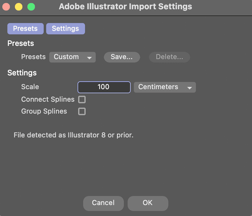
- Click OK to complete the import
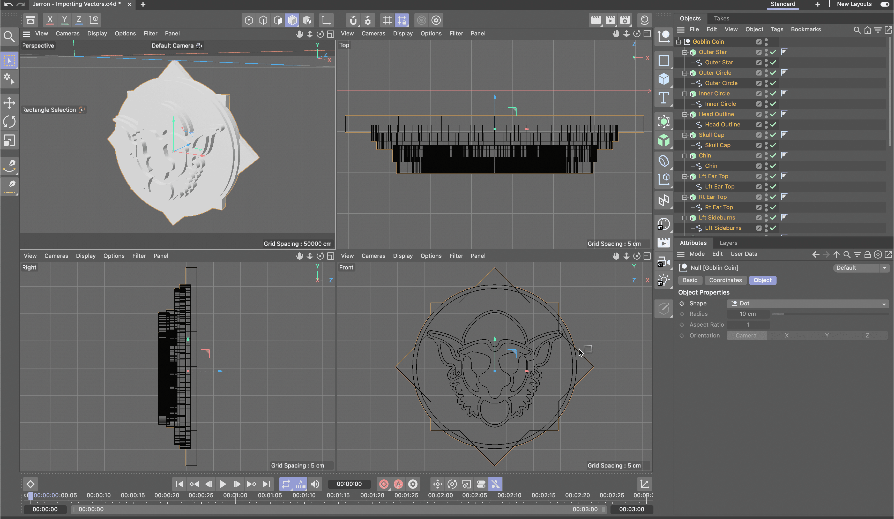
Once imported, hover your cursor over each viewport and press H to automatically frame your geometry perfectly.
Press Cmd–S (Mac) or Ctrl–S (Windows) to save your progress immediately.
Cinema 4D only supports Adobe Illustrator Version 8 and older files for import. Newer Illustrator files must be saved in legacy format before importing.
Import Configuration Steps
Ensures proper sizing for Cinema 4D workspace units
Prevents unwanted modifications during the import process
Automatically frames the imported geometry for better visibility
Cleaning up Imported Files
Imported vector files arrive as organized hierarchies within null objects, with each vector path converted to individual splines. This structure provides excellent flexibility but requires strategic organization for efficient workflow management.
Rename the parent null object with a descriptive name that reflects your project content (e.g., "Company_Logo_Splines" or "Icon_Elements").
Systematically rename each spline using clear, descriptive labels that indicate their function or visual element. This organization becomes crucial when managing complex graphics with multiple components.
Pro Tip: If you struggle to distinguish selected from unselected splines in your scene, enhance visibility by customizing your interface. Navigate to Edit > Preferences > Scheme Color > Activation > Polygons and choose a high-contrast selection color that works better with your monitor and workspace lighting.
If selected splines are difficult to see, customize selection colors through Edit > Preferences > Scheme Color > Activation > Polygons for better visual feedback.
Applying an Extrude Generator to a Spline
Vector imports create two-dimensional splines that remain invisible in renders until converted to 3D geometry. The Extrude Generator transforms these flat paths into dimensional objects while preserving their precise vector curves and allowing for sophisticated material application.
In the Object Manager, select all splines that require extrusion. Use Cmd/Ctrl+click for selective multi-selection or drag-select for adjacent objects.
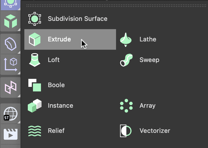
Hold Option (Mac) or Alt (Windows) while choosing Extrude from the Create menu. This modifier automatically parents each extrude generator to its corresponding spline.
With multiple extrude generators selected, adjust their shared attributes simultaneously. Focus particularly on the Offset value, which controls extrusion depth and dramatically affects the final aesthetic impact.
Apply the same systematic naming convention to your extrude generators, creating clear relationships between splines and their 3D counterparts.
For graphics with overlapping elements, translate individual extrusions along different axes to reveal hidden details and create visual separation.
If your original artwork was created using mirroring or clipping operations, adjust the Direction attribute to Z-axis to ensure proper extrusion orientation.
Spline to 3D Conversion Process
Select Multiple Splines
Choose all splines in the Object Manager that need 3D conversion
Apply Extrude with Modifier Key
Hold Option (Mac) or ALT (Windows) while choosing Extrude to apply generators to all selected objects simultaneously
Adjust Extrusion Parameters
Modify Offset attribute for thickness control and Direction attribute to Z for mirrored graphics
Using the Asset Browser for Materials
Cinema 4D Lite's Asset Browser provides access to professional-grade materials and models that can significantly accelerate your project development while maintaining high production values.
Access the comprehensive material library by choosing Window > Asset Browser.
Browse the organized folder structure to locate materials that complement your design vision. Categories range from architectural surfaces to organic textures.
Materials displaying cloud icons are available for immediate download as part of your subscription. Double-click any cloud-marked material to add it to your local library.
Apply materials by dragging them directly onto scene objects. This method provides immediate visual feedback and allows for quick experimentation.
Save your project regularly with Cmd–S (Mac) or Ctrl–S (Windows) to preserve both geometry and material assignments.
Materials with cloud icons in the Asset Browser can be downloaded as part of your Cinema 4D subscription, providing access to professional-quality textures.
Understanding Procedural Textures
Procedural textures represent a fundamental shift from traditional image-based materials. Generated through mathematical algorithms rather than photographic sources, these textures offer unprecedented flexibility for motion graphics and 3D visualization. Unlike bitmap textures that store fixed pixel data, procedural patterns are calculated in real-time based on adjustable parameters and mathematical functions.
This algorithmic approach delivers several key advantages for professional workflows. Procedural textures are inherently resolution-independent, scaling seamlessly from close-up details to wide establishing shots without quality degradation. Their parameter-driven nature allows for infinite variations from a single base texture, enabling rapid iteration and customization that would require multiple bitmap files in traditional workflows.
Common procedural patterns include Perlin noise for organic randomness, cellular automata for natural cell-like structures, and gradient ramps for smooth transitions. These mathematical foundations can simulate everything from surface imperfections and wear patterns to complex natural phenomena, making them invaluable for both realistic and stylized rendering approaches in 2026's demanding visual landscape.
Procedural vs Bitmap Textures
| Feature | Procedural Textures | Bitmap Textures |
|---|---|---|
| Generation Method | Mathematical algorithms | Pixel data storage |
| Scalability | Resolution independent | Limited by pixel resolution |
| Flexibility | Real-time parameter adjustment | Fixed image properties |
| File Size | Minimal storage requirements | Image file dependent |
Creating a Golden Texture
Metallic materials require sophisticated approaches to achieve convincing realism in 3D rendering. Unlike simple surface colors, metals exhibit complex interactions with light through reflection, refraction, and subsurface scattering. Understanding these physical properties allows you to create materials that respond authentically to lighting conditions and camera angles.
In professional 3D workflows, materials serve as the bridge between geometric form and photorealistic appearance. Textures can simulate virtually any real-world surface through careful manipulation of color, reflection, bump mapping, and transparency properties. The following gold material demonstrates advanced techniques applicable to a wide range of metallic and reflective surfaces.
Activate real-time feedback by long-pressing the Render View button and selecting Interactive Render Region. This provides immediate visual feedback as you adjust material properties.
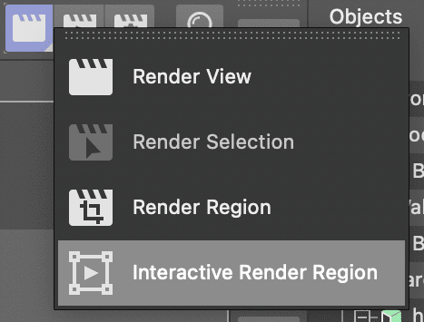
Position the render region window to frame your textured artwork effectively. Maximize the quality slider to leverage your hardware's full rendering capability for accurate material preview.
Open the Material Manager by clicking
 or pressing Shift–F2. Notice the auto-generated gray materials created during the extrusion process.
Create a new foundation by clicking
 .
.Double-click the material icon
 to launch the comprehensive Material Editor.
Access the Color channel and integrate the Lumas shader for superior metallic simulation. Click the texture arrow and navigate to Effects > Lumas.
Click the Lumas text link to reveal shader-specific properties and access the Shader tab.
Configure the base gold color by setting the Color swatch to R = 255, G = 240, B = 0, then close the Color Chooser.
Navigate to Specular 1 and establish the primary highlight color: R = 255, G = 168, B = 0.
Configure Specular 2 for mid-tone highlights: R = 255, G = 199, B = 0.
Set Specular 3 for deep shadow areas: R = 198, G = 145, B = 0.
Enhance surface authenticity through Anisotropy settings: activate the feature and set Y Roughness to 125 for realistic metallic directionality.
Add internal glow by activating Luminance with color values R = 209, G = 153, B = 0 and Brightness = 40.
Optimize reflectance by removing the default reflection layer and adding Beckman for physically accurate metallic reflection.
Fine-tune the Beckman shader's Layer Fresnel properties: select Dielectric, set Strength to 85, and IOR to 1.5 for realistic light behavior.
Activate atmospheric Glow with Outer Strength = 200 and Random = 20 to simulate light interaction.
Close both the Material Editor and Material Manager, then disable Interactive Render Region.
Generate a full-quality render using Cmd–R (Mac) or Ctrl–R (Windows) and save your completed project.
Adjust the quality slider to the highest setting your hardware allows when using Interactive Render Region for real-time material preview feedback.
Gold Material Configuration
Base Color Setup
Apply Lumas shader with RGB values 255, 240, 0 for authentic metallic base appearance
Multiple Specular Layers
Configure three specular layers with varying golden RGB values for realistic light reflection
Advanced Properties
Enable Anisotropy, Luminance, and Glow with specific parameters for professional gold appearance
Rendering a C4D Lite File
Cinema 4D Lite integrates seamlessly with After Effects through the Cineware effect, enabling sophisticated rendering capabilities and dynamic integration with motion graphics workflows. This partnership allows you to leverage After Effects' compositing power while maintaining Cinema 4D's 3D rendering quality.
Launch After Effects and create a new project to house your 3D render integration.
Import your completed C4D file using File > Import and navigate to your saved project file.
Right-click the imported C4D file in the Project panel and select New Comp from Selection for automatic composition setup.
Select the C4D layer in your new composition to reveal its properties and effects.
Locate the automatically applied Cineware effect in the Effect Controls panel—this is your gateway to Cinema 4D integration.
Change the Renderer setting to Current for optimal quality. Note that initial preview generation may require significant processing time depending on your hardware configuration and scene complexity.
Complete your workflow by utilizing either the traditional Render Queue or Adobe Media Encoder for final output, taking advantage of After Effects' extensive format support and optimization options.
After Effects Rendering Workflow
Import C4D File
Use After Effects File > Import to bring Cinema 4D project into AE workspace
Create Composition
Right-click imported C4D file and choose New Comp from Selection for automatic setup
Configure Cineware
Set Cineware effect Renderer to Current in Effect Controls for proper Cinema 4D integration
Setting the Cineware renderer to Current may require significant processing time depending on your computer's hardware capabilities.