Topics Covered in This AutoCAD Tutorial:
Fillet Command
Tutorial Components
Exercise Preview
Get a visual overview of what you'll accomplish in this fillet command tutorial.
Exercise Overview
Understand the practical application of creating a more aesthetically pleasing desk lamp design.
Command Implementation
Learn the step-by-step process of using AutoCAD's Fillet command with various options and settings.
Exercise Preview
Exercise Overview
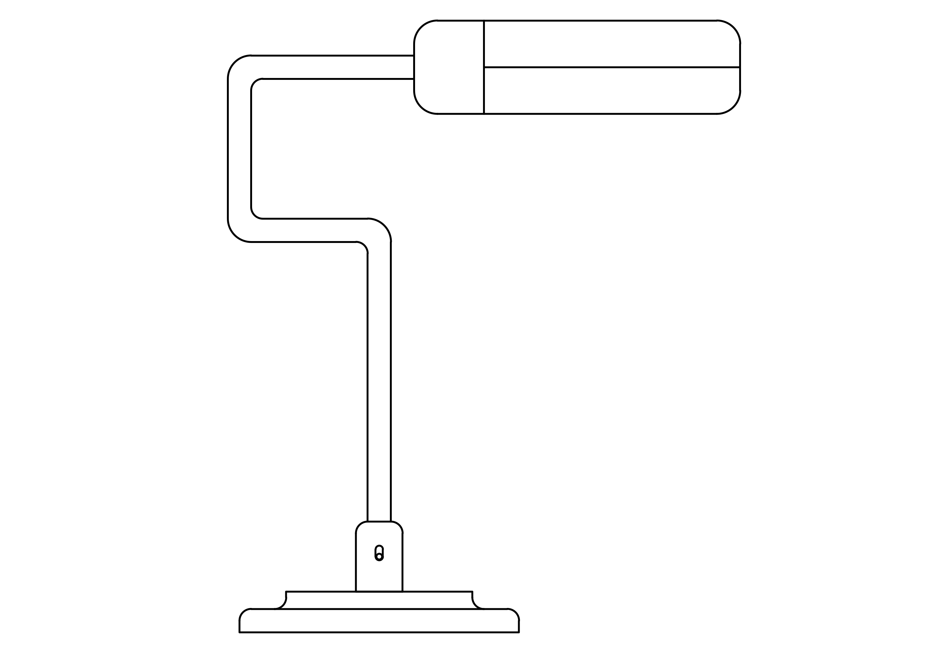
In this comprehensive exercise, you'll master the Fillet command—one of AutoCAD's most versatile tools for creating professional-quality drawings. By applying rounded corners to transform a basic geometric desk lamp into an aesthetically refined design, you'll learn how subtle curves can dramatically improve both the visual appeal and manufacturing feasibility of your CAD models. This technique is essential for product designers, architects, and engineers who need to eliminate sharp edges for safety, aesthetics, or structural reasons.
Transform a basic desk lamp drawing into a more visually appealing design by rounding corners using the Fillet command.
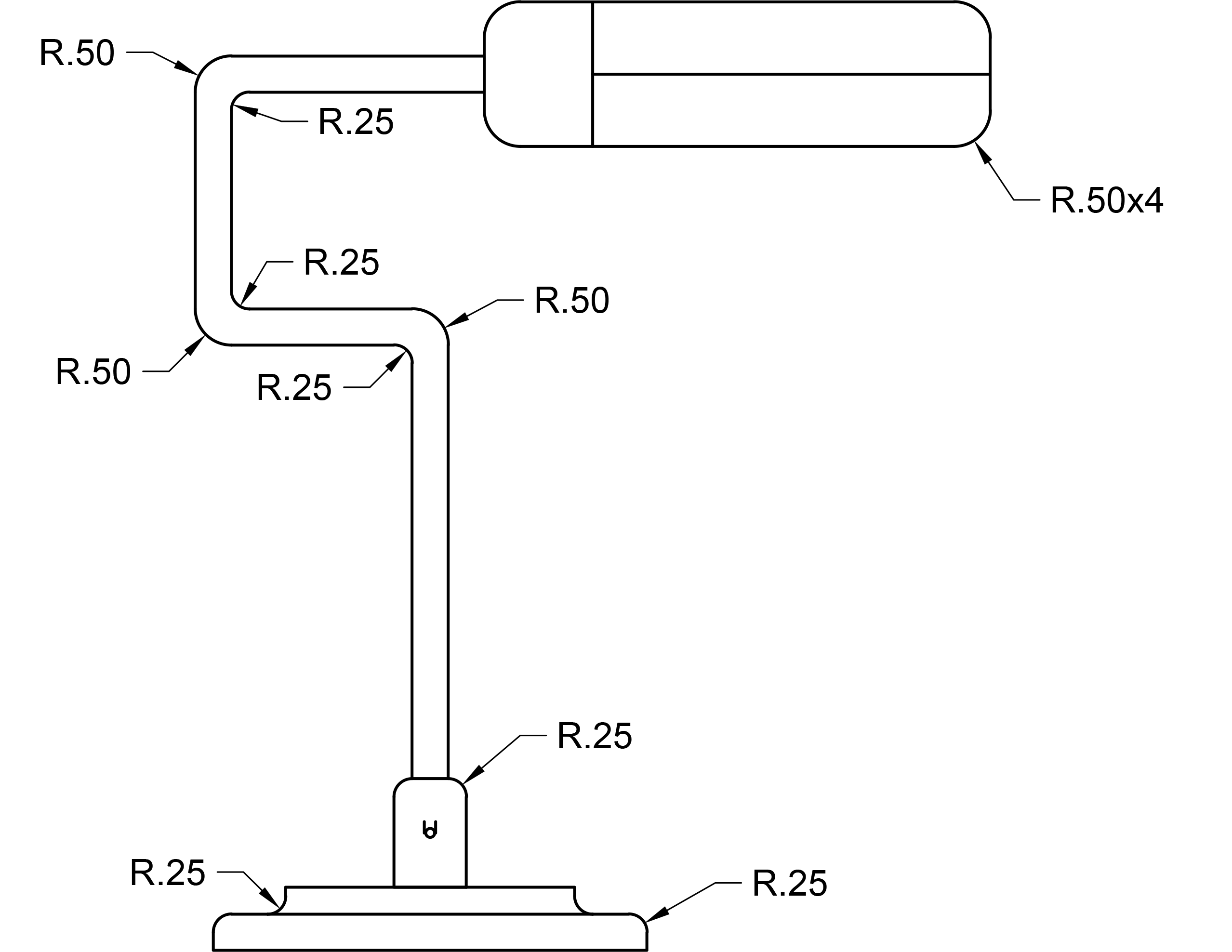
Fillet Radius Values Used
The Fillet Command
The Fillet command remains a cornerstone of professional CAD workflows in 2026, offering multiple approaches to create smooth transitions between intersecting lines and surfaces. Let's explore its full potential through this practical application.
Open the file Fillet-Desk Lamp.dwg.
Press F Enter to initiate the Fillet command. By default, AutoCAD's fillet function operates in single-use mode, terminating after each corner modification. However, professional workflows demand efficiency. In the Command Line, you'll notice a Multiple option—this is your gateway to streamlined productivity. Press M Enter to activate the Multiple option, allowing you to fillet numerous corners and adjust settings dynamically without repeatedly restarting the command.
Next, establish your fillet parameters. Press R Enter to access the Radius option from the Command Line. Enter a radius of .5. Pro tip: With Multiple mode active, you can press R Enter at any time to modify the radius mid-workflow—a significant time-saver when working with complex drawings requiring varying corner radii.
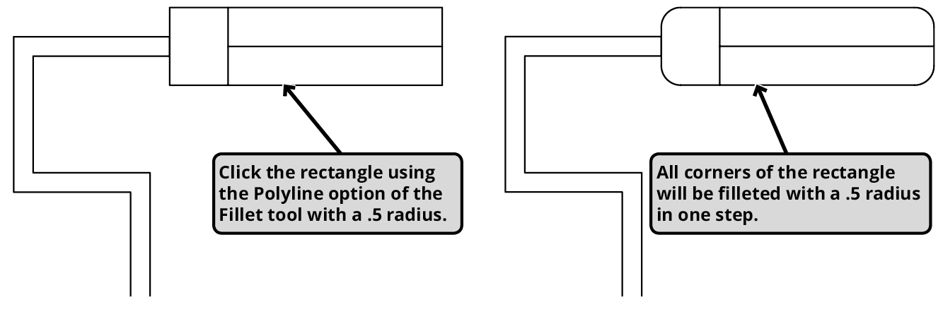
Since the lamp's bulb housing was created using the Rectangle tool, it exists as a single polyline entity. This presents an opportunity to leverage AutoCAD's intelligent object recognition. Press P Enter to select the Polyline option, which enables simultaneous filleting of all polyline corners—a technique that can reduce dozens of individual operations to a single click.
Click anywhere on the rectangular housing at the drawing's top. Watch as AutoCAD instantly applies your specified radius to all four corners simultaneously. This polyline approach is particularly valuable when working with complex shapes containing numerous corners. Remain in the Fillet command for the next operation.
After utilizing the Polyline option, the Fillet command reverts to its standard corner-by-corner mode. This transition allows for precise control over individual intersections. Select the two outer edges forming the upper right corner to create a smooth radius. Note how AutoCAD automatically applies the previously established radius of .5—this parameter persistence eliminates repetitive data entry and maintains consistency across your drawing.

Continue applying the .5 radius to the remaining appropriate corners as illustrated in the reference diagram. This systematic approach ensures uniform corner treatment throughout your design. When you reach the smaller detail areas, press R Enter and specify a radius of .25. This radius reduction demonstrates a key design principle: smaller features require proportionally smaller fillets to maintain visual balance and structural integrity. Keep the Fillet command active as you transition to the final step.
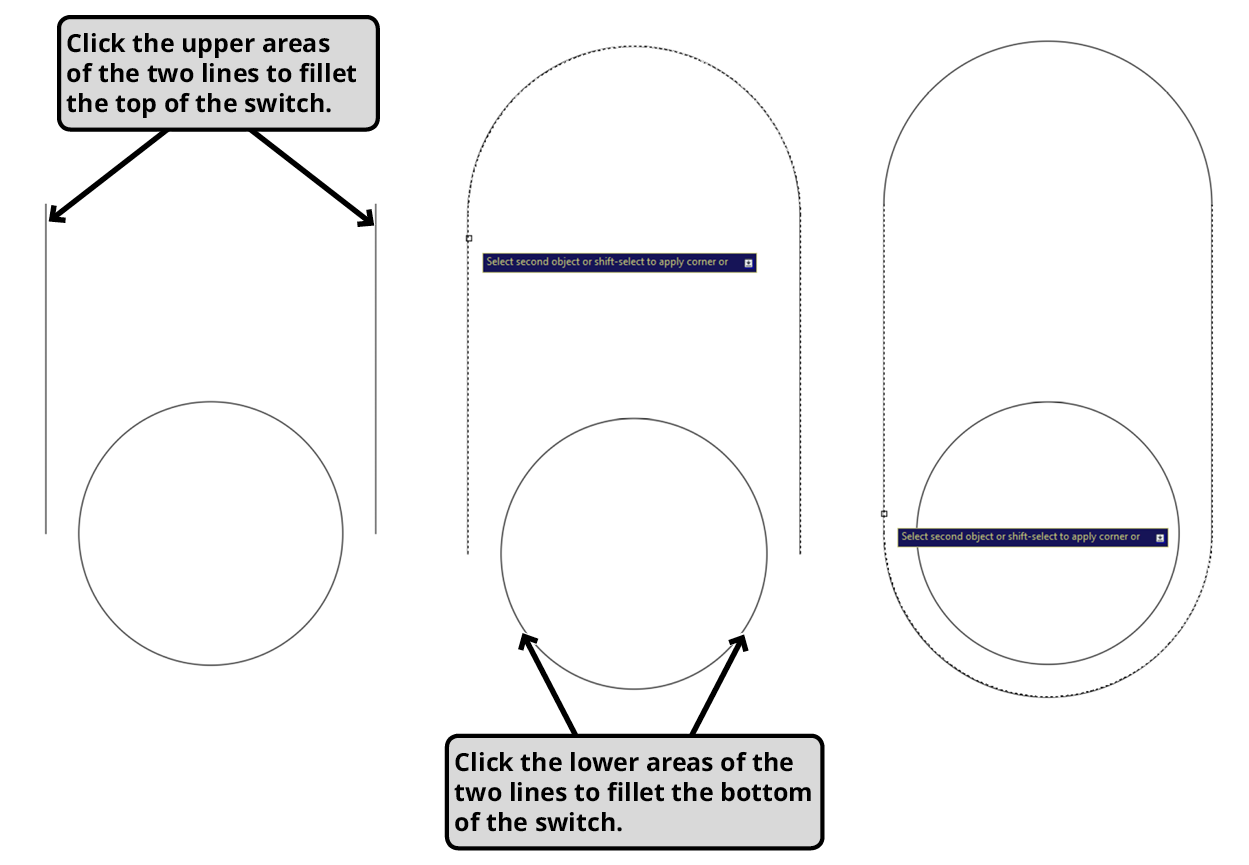
Navigate to the lamp base and locate the small circle flanked by horizontal lines—this will become the lamp's switch mechanism. Here you'll discover one of AutoCAD's most intelligent features: the ability to create connecting curves between non-touching elements. This capability proves invaluable when designing mechanical components, electrical fixtures, or any application requiring smooth transitions between separated elements.
Click the upper ends of both horizontal lines, then repeat for the lower ends as demonstrated below. AutoCAD automatically generates a capsule-shaped profile around the central circle, creating an elegant switch housing. Note that when filleting non-intersecting lines, AutoCAD uses the gap distance as the diameter reference, overriding any user-specified radius. This behavior ensures geometrically correct results while maintaining design intent. Press Enter or Escape to conclude the Fillet command session.
Save and close the file to preserve your work. Consider how these filleting techniques can be applied to your own projects—from architectural details to mechanical components, the principles you've learned here will enhance both the functionality and visual appeal of your designs.
Setting Up the Fillet Command
Open File
Launch the Fillet-Desk Lamp.dwg file to begin the exercise
Start Command
Press F + Enter to initiate the Fillet command in AutoCAD
Enable Multiple Mode
Press M + Enter to activate Multiple option for continuous filleting
Set Radius
Press R + Enter and specify 0.5 as the initial radius value
Using the Multiple option allows you to fillet as many corners as needed and change settings without ending the command until you press ENTER.
Fillet Command Options
| Feature | Standard Mode | Multiple Mode |
|---|---|---|
| Corners per execution | One corner only | Multiple corners |
| Command persistence | Ends after one use | Continues until ENTER |
| Settings changes | Requires restart | Change radius anytime |
Fillet Command Techniques
Polyline Option
Use P + Enter to fillet all corners of a rectangle or polyline simultaneously. Perfect for shapes created with the Rectangle tool.
Individual Corner Method
Click two edges that meet at a corner to create a rounded connection. Works on any two intersecting lines or edges.
Non-touching Lines
Connect separate lines with curved edges. The distance between lines acts as diameter, ignoring user-specified radius.
Fillet Command Workflow
Ensures continuous operation without command restarts
Use R + Enter to specify radius before filleting
Efficiently fillets all four corners simultaneously
Different features may require different radius values
Creates capsule shapes and smooth connections
When filleting non-touching lines, the distance between them acts as the diameter for the fillet, and any user-entered radius value will be ignored.