Topics Covered in This AutoCAD Tutorial:
Using Polar Tracking with the Line Command
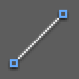
Exercise Preview
![]()
This exercise demonstrates how to combine the Line tool with Polar Tracking to create precise geometric shapes without manual angle entry, significantly improving your drafting efficiency.
Exercise Overview
In this exercise, you'll master one of AutoCAD's most productivity-enhancing features: using the Line tool with Polar Tracking enabled. This powerful drafting aid allows you to snap your cursor to specific angles without manually typing coordinate values into the command line. For professionals working on tight deadlines, this technique can dramatically accelerate your drawing workflow while maintaining precision—a critical combination in today's competitive design environment.
Polar Tracking essentially transforms your cursor into a smart drafting tool that recognizes and locks onto predetermined angles, eliminating the guesswork and repetitive typing that can slow down complex drawings. Once you integrate this technique into your workflow, you'll wonder how you ever drafted without it.
Standard Incremental Angles
Access Tracking Settings at the bottom of the Polar Tracking menu to add additional custom tracking angles beyond the standard incremental angles for specialized drawing requirements.
Using Polar Tracking
- In AutoCAD, close any files you have open to start with a clean workspace.
- From the Start tab, click on the large Start Drawing button to create a new drawing file.
- Navigate to the bottom right Status bar and click on Polar Tracking
 to activate it (the button should turn blue when enabled).
 To the right of the Polar Tracking icon
click the dropdown arrow  and select the incremental angle 45,90,135,180 from the menu that appears.
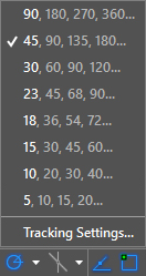
Professional Tip: Incremental angles are mathematically precise angles that divide evenly into a 360° circle, ensuring your drawings maintain geometric accuracy. These standard angles (45°, 90°, 135°, 180°) cover the vast majority of architectural and engineering drawing requirements. For specialized projects requiring custom angles, you can access additional tracking angles by clicking on Tracking Settings at the bottom of this menu.
- Click on the Line tool
 to initiate the Line Command.
 - Type in a first point of 0,0 (the drawing origin) and press Enter to establish your starting coordinate.
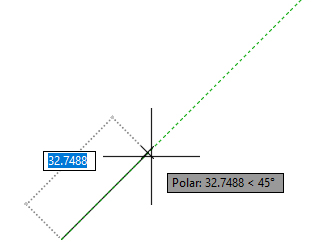
Move your cursor upwards and watch as it automatically snaps to the green vertical 90° Polar Tracking line. When you successfully snap to a Polar angle, AutoCAD displays the distance and angle in a dynamic gray tooltip box:
USE ACTUAL SCREENSHOT
Type in a distance of 10 and press Enter to complete your first line segment.
Efficiency Note: Notice how Polar Tracking eliminated the need to press the Tab key and manually enter the angle—a seemingly small time-saver that compounds significantly over the course of complex drawings. Professional drafters report productivity improvements of 20-30% when fully leveraging this feature.
- For the next line segment, move your cursor up and to the right until it automatically snaps to the 45° green Polar Tracking line. You'll feel a subtle magnetic pull as the cursor locks onto the tracking path.
- Type in a distance of 10 and press Enter to complete the second line segment.
- For the third line segment, move your mouse horizontally to the right to snap to the 0° horizontal angle, then enter a distance of 20 and press Enter.
- Move your cursor downwards for the next line segment, allowing it to snap to the 270° (or -90°) vertical angle, and enter a distance of 10.
- For the next line segment, position your cursor to snap to the 135° angle and enter 10 for the distance.
To complete the final bottom horizontal line segment and create a closed shape, click on the Close option in the command line rather than manually drawing back to the start point.
Excellent work! Now save your file by navigating to File > Save As and browsing to Class Files > AutoCAD Class.
Name the file polar line drawing.dwg and click Save. Keep this file open as we'll build upon these concepts in the next exercise.
Setting Up Polar Tracking
Create New Drawing
Close existing files and click the Start Drawing button from the Start tab to begin with a clean workspace.
Enable Polar Tracking
Click Polar Tracking in the bottom right Status bar until it turns blue, indicating the feature is active.
Select Incremental Angles
Click the arrow next to Polar Tracking and select 45,90,135,180 from the dropdown menu for standard angle increments.
Drawing with Polar Tracking
Start Line Command
Activate the Line tool and enter starting coordinates 0,0 as your first point reference.
Use Visual Snapping
Move cursor to snap to green polar tracking lines. Distance and angle appear in gray information boxes.
Enter Distances Only
With polar tracking active, simply type distances without needing to specify angles manually.
Exercise Drawing Sequence
Vertical Line
Snap to 90 degree vertical line, distance 10
Diagonal Line
Snap to 45 degree angle, distance 10
Horizontal Line
Snap to 0 degree horizontal, distance 20
Return Vertical
Snap to 90 degree downward, distance 10
Final Diagonal
Snap to 135 degree angle, distance 10
Close Shape
Use Close option to complete the polygon
Exercise Completion Checklist
Ensures proper angle snapping functionality
Demonstrates polar tracking efficiency over manual entry
Professional technique for completing enclosed polygons
Proper file organization for continued exercises
Using Polar Tracking eliminates the need to press Tab and manually enter angles, significantly accelerating your drawing workflow while maintaining precision.