Topics Covered in This AutoCAD Tutorial:
Master professional-grade Object Snap techniques—the foundation of precise technical drawing and the difference between amateur sketches and industry-standard CAD work.
Core Learning Objectives
Object Snap Configuration
Learn to activate and deactivate specific snap types including Endpoint, Midpoint, Center, Quadrant, Intersect, Extension, and Tangent snaps for optimal workflow.
Geometric Construction
Master drawing circles, lines, and complex shapes using precise snap points. Create professional technical drawings with accurate measurements.
Advanced Snap Techniques
Utilize Parallel Snap Override and Extension tracking for complex geometric relationships. Learn when different snap types conflict and how to manage them.
Exercise Preview
Tutorial Workflow Overview
Setup Phase
Configure snap settings and place initial circles
Basic Construction
Draw perimeter lines using Tangent and Quadrant snaps
Precision Drawing
Create vertical centerline using Extension tracking
Advanced Techniques
Apply Parallel Snap Override for complex geometry
While Working, Use the Following Snaps & Dimensions
Keep this reference handy throughout the exercise. These snap settings and measurements represent real-world precision requirements you'll encounter in professional drafting environments.
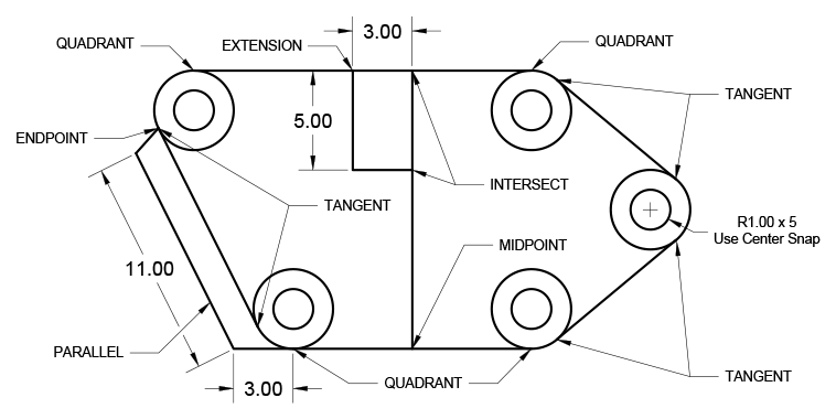
Key Measurements in This Exercise
Snap Type Usage Strategy
| Feature | Active Snaps | Deactivated Snaps |
|---|---|---|
| Initial Setup | Endpoint, Midpoint, Center, Quadrant, Intersect, Extension | None |
| Circle Placement | Center (Primary) | Others as backup |
| Tangent Lines | Tangent, Line endpoints | Center, Quadrant |
| Parallel Override | Parallel (Override), Endpoint | Tangent |
Object Snap in a File
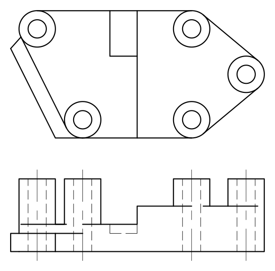
This hands-on exercise will build your muscle memory for the most critical Object Snap functions. Each step builds upon the previous one, creating a complex geometric drawing that demonstrates how professionals combine multiple snap types for maximum precision.
Open the file ObjectSnapStart.dwg. This starter file contains the basic geometry you'll use to practice advanced snapping techniques.
Configure your snap settings by turning on the Endpoint, Midpoint, Center, Quadrant, Intersect, and Extension Snaps. These six snap types handle approximately 80% of precision drawing tasks in professional CAD work, making them essential to master.
Deploy the Circle command
 combined with the Center snap to place circles with a radius of 1 in the center of each existing circle. This technique—concentric circles—appears frequently in mechanical drawings for representing bearings, fasteners, and other hardware components.
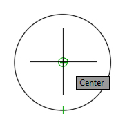
Execute Quadrant Snap functionality to establish the top and bottom edges of your object. Using the Line tool
 , connect the tops of the upper circles and the bottoms of the lower circles. Quadrant snapping ensures your lines connect at precisely 0°, 90°, 180°, and 270° positions on circular objects—critical for maintaining geometric accuracy in technical drawings.
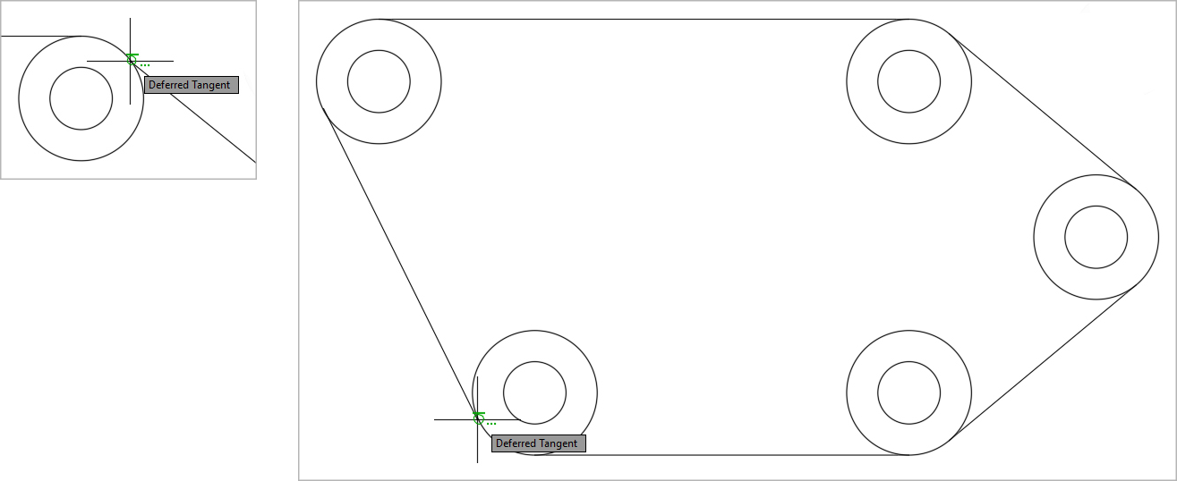
Now comes a crucial workflow adjustment: Turn off the Center and Quadrant Snap and activate Tangent. This step illustrates an important principle—the Tangent Snap conflicts with Center and Quadrant snaps, requiring you to manage your snap settings strategically. Use the Line Command to connect the outer edges of the circles on both sides, completing the outer perimeter. Tangent snapping ensures your lines touch circles at exactly one point, creating smooth, professional-looking connections.
With the Line tool
, snap to the Midpoint of the bottom edge, pull the cursor upward, and utilize the 90° Polar Tracking line to snap to the Intersect point at the top edge of the object. This creates a perfectly vertical centerline connecting the top and bottom of your object. Press Enter or Escape to end the Line command. This combination of Midpoint and Intersect snapping with Polar Tracking represents the kind of multi-tool coordination that separates efficient CAD operators from beginners.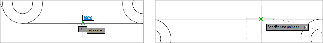
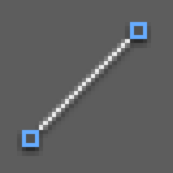
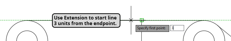
Press Enter to restart the Line command for this advanced Extension Snap technique. Without clicking, hover your cursor over the upper Endpoint of the previous line segment to establish the extension reference. Pull the cursor to the left until the horizontal tracking line appears. The Extension indicator may or may not display in the Dynamic Input, but the Extension Object Snap remains active as long as it's enabled in your Object Snap menu. While maintaining the Polar Tracking line visibility, type 3 and press Enter. A new line segment will begin exactly 3 units to the left of your reference line. Continue by pulling downward on the 90° tracking line and entering a distance of 5. Pull rightward on the horizontal Polar Tracking line until it intersects with the vertical line and click using the Intersect snap. Press Enter or Escape to end the Line command. This sequence demonstrates how Extension Snap allows you to project beyond existing geometry—a powerful technique for creating construction lines and layout guides.
Press Enter to restart the Line command and reconfigure your snap settings. In the Object Snap menu, reactivate the Center and Quadrant snap while unchecking Tangent. This snap management demonstrates the dynamic approach professionals use—constantly adjusting tools to match the task at hand. Snap and click on the lower quadrant of the lower left outer circle and draw a 3 unit line segment to the left along the horizontal tracking line. This precision placement ensures your new geometry aligns perfectly with the existing circular elements.
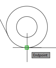
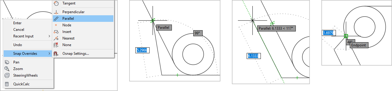
This final step introduces the sophisticated Parallel Snap Override technique. The next line segment must be parallel to the left edge of the object, but determining the exact angle manually would be time-consuming and error-prone. While still in the Line command, Right-click and select the Snap Overrides submenu from the context menu, then activate the Parallel Snap Override. Without clicking, touch your cursor to the left edge of the object—this "teaches" AutoCAD the angle you want to match, and the Parallel Snap symbol will appear. Pull the cursor back to the right and snap to the Parallel tracking line that now appears. Enter 11 for the distance, and your new line segment will be perfectly parallel to the left edge of the object. For the final line segment, click on the endpoint where the left edge of the object meets the upper left circle to complete the drawing. Press Enter or Escape to end the Line Command. Note that Snap Override automatically deactivates after one use—a built-in safety feature that prevents accidental repeated applications.
Phase 1: Initial Setup and Circle Placement
File Setup
Open ObjectSnapStart.dwg and activate Endpoint, Midpoint, Center, Quadrant, Intersect, and Extension snaps through the Object Snap menu.
Circle Construction
Use Circle command with Center snap to place 1-unit radius circles in the center of each existing circle, creating concentric geometry.
Horizontal Connections
Apply Quadrant snap with Line tool to connect tops of upper circles and bottoms of lower circles, forming horizontal edges.
Tangent snap will not function when Center or Quadrant snaps are active. Always deactivate conflicting snaps before proceeding to tangent line construction.
Phase 2: Perimeter and Centerline Construction
Tangent Perimeter
Deactivate Center and Quadrant, activate Tangent snap. Use Line command to connect outer circle edges, completing the object perimeter.
Vertical Centerline
Snap to bottom edge Midpoint, use 90-degree Polar Tracking to create vertical line to top edge Intersect point.
Extension Tracking Setup
Start new Line command, snap to upper Endpoint of previous segment, pull left until horizontal tracking appears for Extension snap preparation.
The Extension snap activates automatically when checked in Object Snap menu. The word 'Extension' may not appear in Dynamic Input, but tracking lines indicate active status.
Phase 3: Advanced Geometry with Measurements
Measured Extensions
While Extension tracking is active, type '3' and press Enter to create line segment 3 units left. Pull downward and enter '5' for vertical segment.
Intersect Completion
Pull right on horizontal tracking until intersection with vertical line, click using Intersect snap to complete the rectangular extension.
Parallel Snap Override vs Permanent Activation
Phase 4: Parallel Construction and Completion
Snap Reconfiguration
Reactivate Center and Quadrant snaps, deactivate Tangent. Snap to lower quadrant of lower left circle, draw 3-unit horizontal line segment.
Parallel Override Application
Right-click, select Snap Overrides, activate Parallel. Touch cursor to left edge to establish parallel reference, then draw 11-unit parallel segment.
Final Connection
Click endpoint where left edge meets upper left circle to complete drawing. Parallel Snap Override automatically deactivates after use.