Topics Covered in This AutoCAD Tutorial:
Hatch Cross Section
Exercise Preview
Core AutoCAD Hatch Concepts
Pattern Application
Learn to apply predefined hatch patterns to enclosed areas using the Hatch command. ANSI31 pattern is standard for cross sections.
Associative Hatching
Understand how hatches automatically adjust when their boundary objects are modified, maintaining accuracy in technical drawings.
Layer Management
Master moving hatches to appropriate layers without changing the current drawing layer, improving drawing organization.
Exercise Overview
In this comprehensive exercise, you'll master the essential Hatch command—one of AutoCAD's most powerful tools for creating professional technical drawings. You'll learn to fill areas with predefined patterns that communicate material properties and section views with industry-standard clarity. This skill is fundamental for any CAD professional working in engineering, architecture, or manufacturing design.
Hatch Command Workflow
Activate Hatch Command
Press H + Enter, use the Hatch button in Draw Panel, or access from toolbar to open Hatch Creation Ribbon
Select Internal Points
Click inside closed areas to define hatch boundaries. Multiple areas can be selected before pressing Enter
Configure Properties
Use Hatch Editor to modify layer assignment, pattern type, and other properties after creation
Avoid clicking in the same area multiple times as this creates overlapping hatches. Each click adds a new hatch layer to the same location.
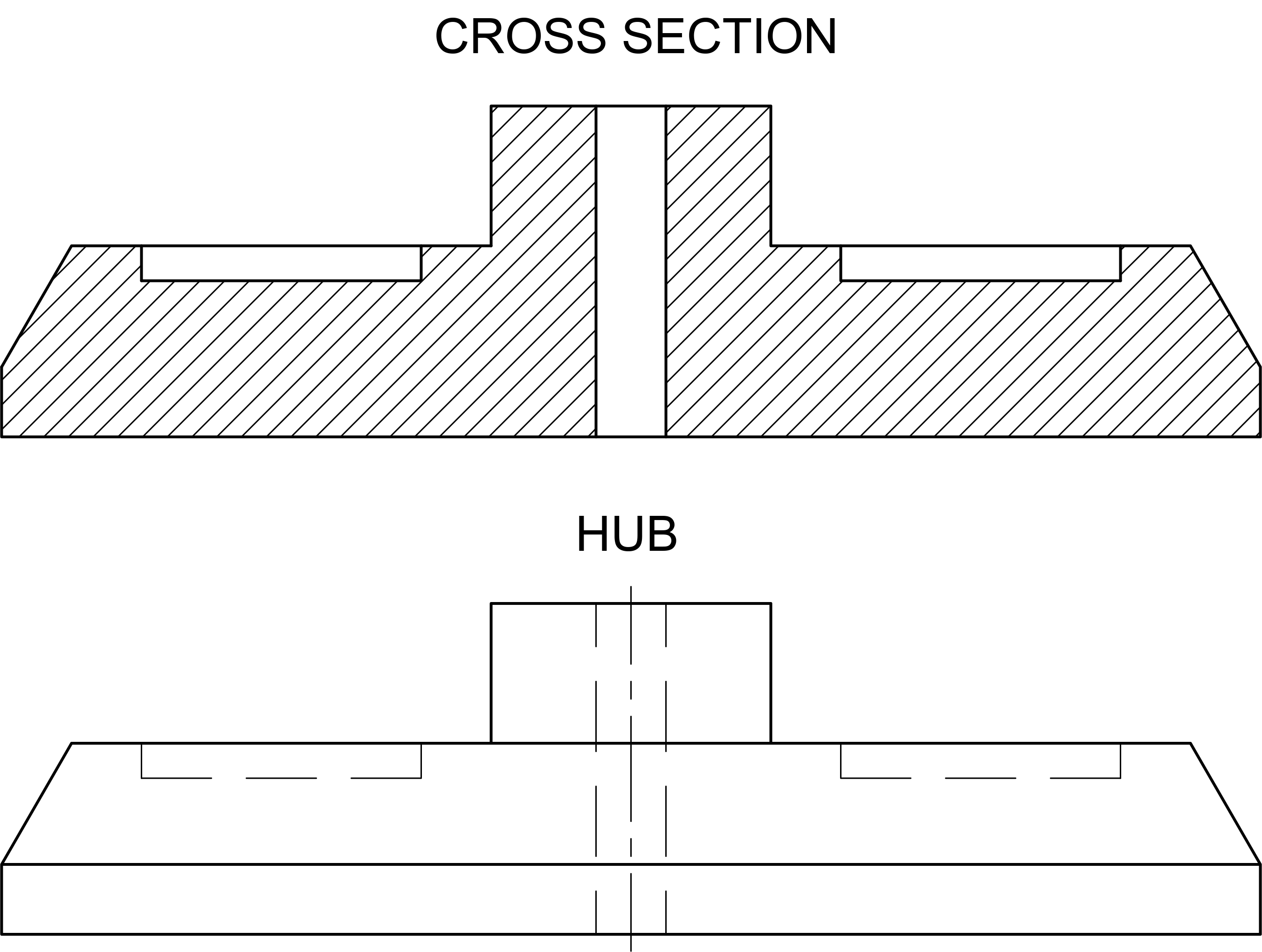
Cross Section Hatching
Begin by opening the file Hatch-Hub Section.dwg. This drawing contains a mechanical part that demonstrates real-world hatching applications.
Launch the Hatch command using the keyboard shortcut H Enter—the fastest method preferred by experienced users. Alternatively, click the Hatch button
 in the Draw Panel or Toolbar. The Hatch Creation Ribbon tab appears immediately, providing access to all hatching parameters before you commit to the pattern.
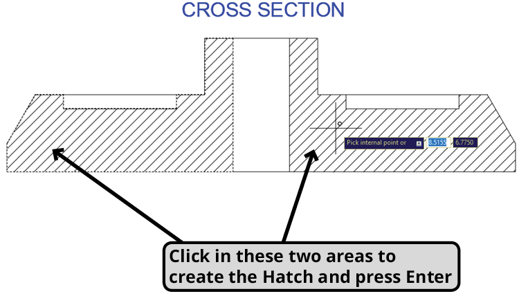
When AutoCAD prompts you to Pick internal point, precisely click within the two enclosed areas of the cross section shown in the diagram below, then press ENTER to execute the command. AutoCAD's boundary detection algorithm requires you to click inside fully closed areas—any gaps in the boundary will prevent proper hatch creation (though Gap Tolerance settings can address minor gaps, as we'll explore in the next exercise).
Professional tip: You can select multiple areas in a single hatch operation, and AutoCAD treats them as one unified object for editing purposes. However, avoid clicking the same area twice, as this creates overlapping hatches that can cause printing and display issues.
For this exercise, we're using AutoCAD's default ANSI31 pattern—the industry standard for indicating cross-sectioned surfaces in technical drawings. This diagonal line pattern has been the engineering standard for decades and immediately communicates "cut surface" to anyone reading your drawings.
Now we'll demonstrate proper layer management—a critical skill for maintaining organized, professional drawings. Select the hatch you just created to activate the Hatch Editor ribbon tab. Expand the Properties Panel to reveal advanced hatch controls.
Notice the Layer dropdown menu—this powerful feature allows you to reassign the hatch to a different layer without changing your drawing's current layer setting. Change the layer assignment from Object to Hatch. Watch as your cross-section hatch immediately adopts the visual properties (color, linetype, lineweight) of the Hatch layer. This layer-based organization is essential for complex drawings where you need to control the visibility and plotting of different drawing elements.
Here's where AutoCAD's intelligence truly shines. With the hatch still selected, examine the Properties Palette and note the area value: 10.4952. This automatic area calculation is invaluable for material estimates and engineering calculations.
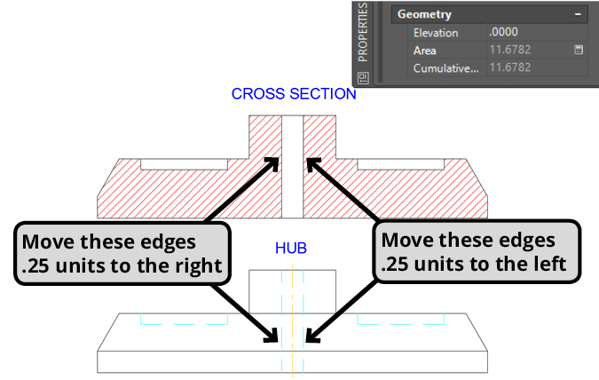
More importantly, your hatch is associative by default—meaning it maintains a dynamic relationship with its boundary objects. This parametric behavior is crucial for design iterations and revisions. Let's test this: use the Move command to relocate the vertical edges of the central hole inward by 0.25 inches on each side, affecting both the cross section and hub views.
Observe how the hole narrows and the hatch automatically recalculates its boundary to match the new geometry. The centerline in the hub view also shifts because it was created with AutoCAD's intelligent Centerline tool, which maintains its centered position relative to the moved edges. Select the hatch again and check the Properties Palette—the area now reads 11.6782, reflecting the geometry change automatically.
Understanding hatch associativity gives you complete control over your drawing's behavior. While hatches maintain associative relationships by default, they function as independent objects with their own properties and editing capabilities.
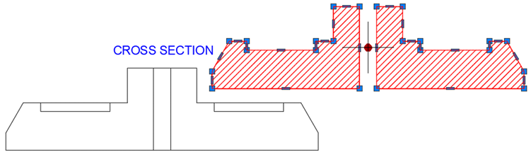
You can deliberately break this association by deselecting the Associative button in the Hatch Editor ribbon, or it may happen inadvertently if you delete or significantly modify the boundary objects. Once disassociated, the hatch displays standard AutoCAD grips and behaves like any other geometric object—but you cannot restore the associative relationship.
To demonstrate this flexibility, select your hatch and click the central round grip, then drag it away from the boundary objects. Notice the grip pattern around the hatch perimeter—these allow precise manual editing when associativity isn't needed. Press CTRL–Z to undo this operation and maintain the associative relationship for this exercise.
Complete this exercise by saving and closing the file. You've now mastered the fundamental concepts of professional hatching: pattern application, layer management, associative behavior, and area calculation—skills you'll use in virtually every technical drawing you create.
Hatch Area Changes During Exercise
Associative vs Non-Associative Hatches
Hatch Modification Process
Create Initial Hatch
Apply ANSI31 pattern to cross section areas
Change Layer Assignment
Move hatch from Object layer to Hatch layer
Modify Boundary Objects
Move vertical edges inward by 0.25 inches each
Verify Area Update
Check Properties Palette for new area calculation
Use the Hatch Editor's Properties Panel to change hatch layers without affecting the current drawing layer. This maintains organized layer structure in complex drawings.
Exercise Completion Checklist
Ensure you have the correct drawing file before starting
Click inside each enclosed area and press Enter
Use Properties Panel in Hatch Editor for layer change
Properties Palette should show 10.4952
Apply to both Cross Section and Hub views
Demonstrates associative hatch functionality
Preserve your work for future reference