Topics Covered in This AutoCAD Tutorial:
Polylines, Offset
Exercise Preview
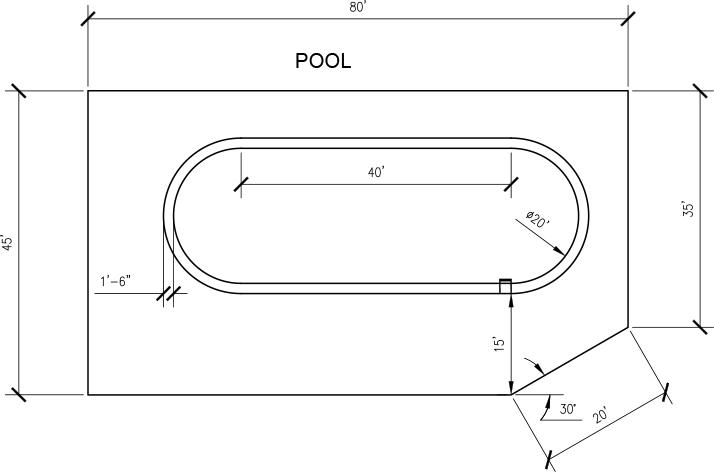
Exercise Overview
In this exercise, you'll master two fundamental AutoCAD tools that are essential for efficient drafting: the Polyline and Offset commands. The Polyline tool creates connected line segments that function as a single object—a crucial advantage over individual line segments when you need to modify, move, or offset complex shapes. You'll also discover how the Offset tool creates precise parallel copies of polylines, a technique that's indispensable for architectural detailing, mechanical design, and any application requiring consistent spacing between elements.
Line Tool vs Polyline Tool
| Feature | Line Tool | Polyline Tool |
|---|---|---|
| Object Treatment | Separate segments | Single connected object |
| Editing Efficiency | Edit each segment individually | Edit entire shape as one unit |
| Offset Capability | Offset each segment separately | Offset entire perimeter at once |
Using the Polyline & Offset Tools
Follow these steps to build a complete pool design while learning professional drafting techniques that you'll use throughout your AutoCAD career.
Start a new drawing based on the Architectural-Imperial.dwt template and save the file as Pool.dwg. This template provides the proper units and settings for architectural work, establishing a professional foundation for your drawing.
Set the Polar Tracking angle to 35˚. This angle will guide your cursor movements and ensure precise angular construction throughout the exercise.
Access the Polyline (PLINE) tool by clicking its button
 on the Draw Panel or Ribbon, or use the keyboard shortcut PL Enter for faster workflow.
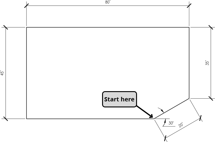
Draw a polyline following the diagram below to create the patio perimeter around the pool. Notice that the Polyline tool initially behaves identically to the Line tool, but creates a single, connected object instead of individual segments. Complete the shape by pressing C Enter to use the Close option, which automatically connects the final segment to your starting point with perfect precision.
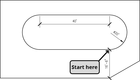
Now you'll create the pool itself using polylines that combine both straight and curved segments. Repeat the Polyline Command
. Use the Extension snap to precisely place your start point 16'-6"above the lower-right corner of the patio. Once you've established the start point, the Command Line will display available options—this dynamic interface is key to AutoCAD's efficiency.For the first segment, you'll create an arc. Press A Enter to activate the Arc option. AutoCAD's polyline arcs are constructed using two points that define the arc's diameter, making them intuitive to create. Pull straight up along the X-axis and enter 20
'to create a semicircular arc with a 20-foot diameter.
The polyline tool remains in Arc mode, as indicated by the different command options now visible. This mode persistence allows you to create multiple connected arcs efficiently. Press L Enter to return to Line mode for the next segment. Pull left along the Y-axis and enter 40
'to create the straight edge of the pool.For the final segment, return to Arc mode by pressing A Enter. Notice that the close option now requires CL instead of C—AutoCAD distinguishes between commands that share the same starting letter to prevent ambiguity. Press CL Enter to close the polyline with a matching arc segment, completing your pool shape.

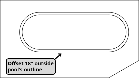
Next, you'll use the powerful Offset command to create a tiling border around the pool. This demonstrates one of the primary advantages of polylines: the ability to offset complex shapes as a single entity, maintaining perfect geometric relationships throughout the operation.
Press O Enter to start the Offset command. Enter 18
"for the Offset Distance. Unlike most Modify tools, Offset requests the distance first, then the object selection. This workflow is designed for efficiency—you can quickly repeat the command with different distances by double-tapping the spacebar.Select the pool's edge as the object to offset, then click anywhere outside the pool to specify which side should receive the offset copy. Press Enter or Escape to complete the command. The result is a perfectly parallel copy that maintains the exact shape relationships of your original polyline.
Setting Up Your AutoCAD Drawing
1Create New Drawing
Start with Architectural-Imperial.dwt template and save as Pool.dwg for organized project management
2Configure Polar Tracking
Set Polar Tracking angle to 35 degrees to ensure precise angular measurements throughout the exercise
3Access Polyline Tool
Use PLINE button on Draw Panel, toolbar, or type PL Enter for quick command access
Command Line EfficiencyThe Polyline tool behaves like the Line tool by default, but offers advanced options through Command Line inputs like Arc mode and Width adjustments.
Offsetting Perimeters
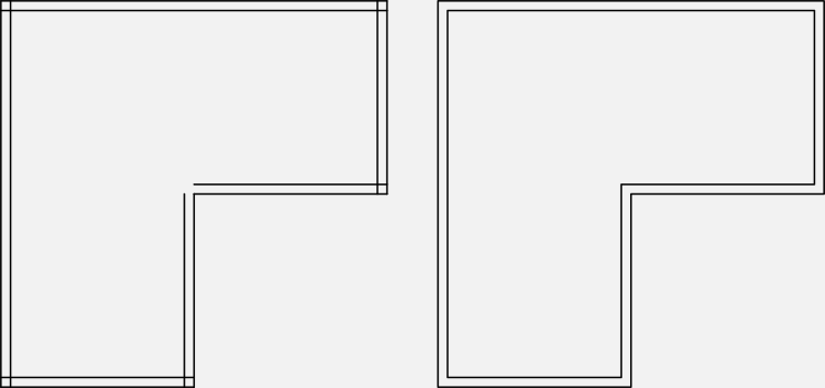
This comparison illustrates why polylines are superior for complex shapes. The image below shows a perimeter created with individual Line segments (left) versus one made with the Polyline tool (right). Notice how the line-based approach creates gaps and overlaps when offset, while the polyline maintains perfect continuity:
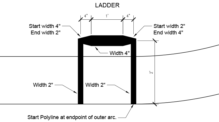
For the final step, you'll explore polylines' advanced capability to incorporate variable line weights within a single object. This technique is invaluable for creating detailed drawings without relying solely on layer-based lineweight assignments. You'll construct a pool ladder that demonstrates how polylines can transition smoothly between different widths.
Change your current layer to Misc to organize the drawing properly. Start the Polyline command and snap to the lower-right endpoint of the pool's outer offset line. Once you've established the start point, notice that the Width option appears in the Command Line—this option only becomes available after you've defined the polyline's starting location.
Type W Enter to access the Width option. Enter 2 for the starting width. AutoCAD requires both starting and ending widths for each segment, even when they're identical—this gives you complete control over tapered segments. Press Enter to accept 2" as the ending width as well. Pull up along the X-axis and enter 2" for the distance.
Press W Enter again to modify the width for the next segment. Press Enter to maintain the 2" starting width, but enter 4" for the ending width, creating a tapered segment. Pull left along the Y-axis and enter 4" for the segment length. Continue with a 1" segment to the left without changing the width—the polyline will maintain the previous ending width of 4".
For the next width transition, type W Enter again. Keep the 4" starting width by pressing Enter, then enter 2" for the ending width. Create the final segment by pulling down along the Y-axis and entering 2".
Important: Don't end the polyline command yet. The width setting persists across polyline sessions, so you must reset it to avoid affecting future polylines. Press W Enter one final time and set both the starting and ending widths to 0 to restore the default behavior. Now press Escape or Enter to end the command.
Save and close your file. You've now completed a comprehensive exercise that demonstrates both basic polyline creation and advanced techniques like variable width segments and offset operations—skills that form the foundation of professional AutoCAD drafting.
Polyline Width Variations