Topics Covered in This AutoCAD Tutorial:
Ortho Tracking, Additional Polar Angles
Ortho Tracking (F8 in the Status Bar)
Ortho is short for orthographic, a fundamental drawing principle where all lines are constrained to vertical or horizontal orientations. This technique forms the backbone of technical drafting and architectural drawing. When Ortho Tracking is active, AutoCAD restricts all drawing angles to precisely 0° or 90°—eliminating the guesswork and potential errors that come with freehand cursor movement.
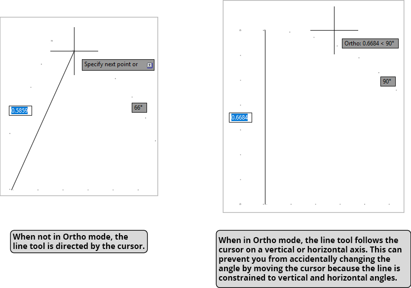
When you're using the Line tool  , Ortho Tracking transforms your workflow dramatically. Instead of following your cursor's every movement (as with Polar Tracking), lines snap automatically to vertical or horizontal paths based on your general cursor direction. This constraint system serves multiple purposes: it accelerates drawing speed by reducing cursor precision requirements, prevents accidental angle deviations that plague manual drafting, and ensures geometric accuracy in your technical drawings.
Since the majority of lines in professional drafting—whether architectural plans, mechanical drawings, or electrical schematics—follow orthographic principles, mastering Ortho Tracking is essential for efficient CAD work. The beauty of AutoCAD's implementation lies in its flexibility: you can seamlessly toggle between Ortho and Polar Tracking modes by clicking the Status Bar buttons or using the F8 (Ortho) or F10 (Polar) keyboard shortcuts, even mid-command without interrupting your current operation.
Ortho is short for orthographic. In orthographic drawing, all lines are either vertical or horizontal, creating precise technical drawings.
Ortho Tracking Angles
Ortho Tracking Benefits vs Limitations
Additional Polar Angles
While Chapter 2 covered the fundamentals of incremental Polar Tracking angles, professional drafting often demands more sophisticated angular control. This is where Additional Angles become invaluable—custom angles that create precise tracking lines for specialized drawing requirements such as isometric projections, architectural roof pitches, or mechanical part geometries.
To configure Additional Angles in AutoCAD, expand the Polar Tracking menu in the Status Bar and select Tracking Settings. The resulting dialog box provides a New button for adding custom angles to your tracking arsenal. The system includes an Additional Angles checkbox—a crucial feature that allows you to temporarily deactivate these custom angles without deleting them. This prevents unwanted snapping to irrelevant tracking lines when working on different drawing elements, maintaining precision while preserving your custom angle library for future use.
![]()
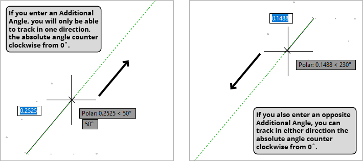
Understanding Additional Angles requires grasping their absolute nature—they're measured counter-clockwise from the horizontal baseline at 0°, not relative to your current drawing position. This creates a limitation: each angle produces only one directional tracking line. For maximum flexibility, you'll typically want bidirectional tracking capability, which requires calculating and entering the opposite angle.
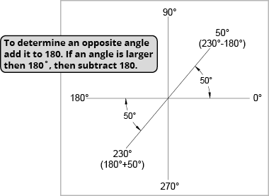
The mathematics are straightforward: for angles less than 180°, add 180° to find the opposite. For a 50° angle, the opposite is 230° (50+180). For angles greater than 180°, subtract 180°—so 230° becomes 50° (230-180). Professional tip: create a quick reference sketch showing your common angles and their opposites. This saves time during complex projects and reduces calculation errors when working under deadline pressure.
Setting Up Additional Angles
Access Tracking Settings
Expand the Polar Tracking menu in the Status Bar and select Tracking Settings to open the dialog box.
Add New Angle
Click the New button in the Tracking Settings dialog to add your custom Additional Angle value.
Calculate Opposite Angle
Determine the opposite direction by adding 180° to angles under 180° or subtracting 180° from angles over 180°.
Manage Activation
Use the Additional Angles check box to activate or deactivate custom angles without deleting them.
For angles under 180°, add 180. For angles over 180°, subtract 180. Example: 50° opposite is 230° (50+180), and 230° opposite is 50° (230-180).
Additional vs Incremental Angles
| Feature | Additional Angles | Incremental Angles |
|---|---|---|
| Direction | Absolute from 0° | Relative increments |
| Tracking Lines | Single direction only | Multiple directions |
| Setup Method | Custom entry via New button | Predefined increments |
| Best Use Case | Specific custom angles | Standard angular divisions |
Additional Angles Best Practices
Ensures you can track in both directions when moving the cursor
Prevents accidental snapping to wrong tracking lines during regular drafting
Visual reference helps determine correct opposite angles and relationships
Verify tracking behavior matches your drafting requirements