Topics Covered in This AutoCAD Tutorial:
Entering Coordinates, Angles, & the UCS
Exercise Preview
This tutorial builds foundational skills in coordinate entry, angle measurement, and coordinate system management - essential for precise technical drawing in AutoCAD.
Coordinates
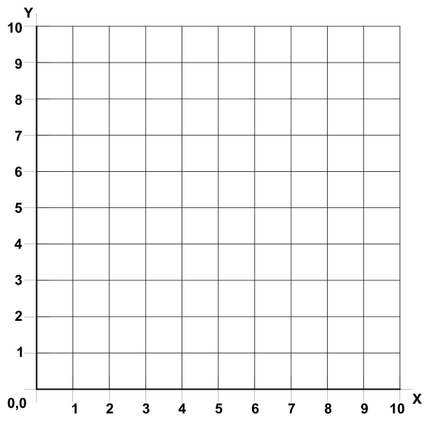
Every AutoCAD drawing begins with a foundational XY plane anchored at the absolute origin point 0,0 on a Cartesian coordinate grid system. Named after mathematician René Descartes, the Cartesian system provides the mathematical framework for precise object placement in both 2D and 3D space. While this tutorial focuses exclusively on 2-dimensional drafting techniques, it's worth noting that the Z-axis becomes essential for 3D modeling in the full version of AutoCAD—a capability that remains unavailable in AutoCAD LT even in 2026.
Understanding coordinate positioning is fundamental to professional CAD work. Every object, line, and point in your AutoCAD drawing occupies a specific location on this XY grid. When working in 2D, you're essentially viewing your drawing from directly above, where the X-axis runs horizontally and the Y-axis extends vertically. AutoCAD follows the standard X, Y coordinate entry format. For instance, to specify a point located 3 units right and 5 units up from the origin, you would input 3,5.
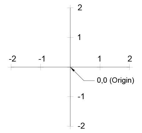
The coordinate system follows logical directional conventions: positive X values extend to the right of the Origin Point, while negative X values move leftward. Similarly, positive Y values are positioned above the Origin Point, and negative Y values fall below it. To place a point 3 units left and 2 units down from the origin, you would enter –3, –2. This consistent system enables precise positioning regardless of drawing complexity.
AutoCAD offers two coordinate input methods that significantly impact your workflow efficiency. Absolute coordinates reference all measurements from the Origin Point, providing consistent positioning across the entire drawing. Relative coordinates, set as the default, calculate positions relative to your last input or current tool context. This distinction becomes crucial when using tools like Rectangle—with relative coordinates active, you simply input width and height from your starting point. With absolute coordinates, you must specify the exact XY location of the opposite corner.
To access these settings, right-click the Dynamic Input button ![]() on the Status Bar, select Dynamic Input Settings, then click Settings under pointer input. Professional tip: keep Dynamic Input enabled, as relative coordinates streamline most drafting tasks. Disabling it forces AutoCAD back to absolute coordinates, which can slow your workflow unnecessarily.
on the Status Bar, select Dynamic Input Settings, then click Settings under pointer input. Professional tip: keep Dynamic Input enabled, as relative coordinates streamline most drafting tasks. Disabling it forces AutoCAD back to absolute coordinates, which can slow your workflow unnecessarily.
Understanding Coordinate Entry
Basic Format
Coordinates are entered as X,Y format. For point at X=3, Y=5, type 3,5
Positive Values
Positive X values extend right of origin, positive Y values extend above origin
Negative Values
Negative X values extend left of origin, negative Y values extend below origin
Absolute vs Relative Coordinates
| Feature | Absolute | Relative |
|---|---|---|
| Reference Point | Origin Point (0,0) | Previous point or object |
| Default Setting | When Dynamic Input off | Default with Dynamic Input on |
| Rectangle Tool | Enter opposite corner XY | Enter width and height |
| User Preference | Less commonly used | Generally more useful |
Right-click the Dynamic Input button on Status Bar, select Dynamic Input Settings, then press Settings under pointer input to configure coordinate behavior.
Angles
AutoCAD's angle measurement system follows the mathematical standard of counter-clockwise rotation from the 0° horizontal baseline. This convention aligns with engineering and architectural practices worldwide, ensuring consistency when sharing drawings with international teams or clients.
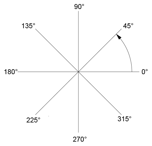
Like coordinates, angles can be measured as either relative or absolute values depending on your current task. Relative angles measure from your previous line segment or current polar direction, while absolute angles always reference the standard 0° horizon. This flexibility allows for both precise geometric construction and intuitive sketching workflows.
Angle Measurement System
Counter-Clockwise Direction
All angles in AutoCAD are measured counter-clockwise from the 0 degree horizon line.
Flexible Reference
Angles can be relative to polar angle or previous line segment, or absolute from 0 degree horizon.
Forced Absolute or Relative Values Using # or @
Even with default settings in place, you'll occasionally need to override AutoCAD's coordinate behavior for specific inputs. These keyboard prefixes provide instant control over coordinate interpretation.
Type # (Shift+3) before any coordinate or angle entry to force absolute positioning relative to the Origin Point or 0° horizon line. This proves invaluable when you need to place an object at a precise location regardless of your current position or previous inputs. Conversely, typing @ (Shift+2) forces relative values, though this is rarely necessary since relative mode is the default setting. These override commands become second nature with practice and significantly enhance precision in complex drawings.
Coordinate Override Symbols
| Feature | # (Shift 3) | @ (Shift 2) |
|---|---|---|
| Function | Forces absolute values | Forces relative values |
| Reference Point | Origin Point or 0° horizon | Previous point or segment |
| Usage Frequency | When absolute needed | Rarely needed (default) |
Type the override symbol immediately before entering coordinate or angle values to force the desired coordinate mode for that specific entry.
UCS Icon
The User Coordinate System (UCS) represents one of AutoCAD's most powerful yet potentially problematic features. While the UCS allows you to reposition the Origin Point and reorient the X, Y, and Z axes for specialized workflows, improper use can create confusion and drafting errors.
In 2D drafting, the UCS Icon ![]() serves as a visual indicator of your current X and Y axis orientation. Its position varies based on your settings—it may appear at the screen's bottom-left corner, at the current Origin Point, or remain hidden entirely. Access these options through the View menu by selecting Display > UCS. When On is highlighted, the icon remains visible; when Origin is highlighted, the icon positions itself at the Origin Point.
serves as a visual indicator of your current X and Y axis orientation. Its position varies based on your settings—it may appear at the screen's bottom-left corner, at the current Origin Point, or remain hidden entirely. Access these options through the View menu by selecting Display > UCS. When On is highlighted, the icon remains visible; when Origin is highlighted, the icon positions itself at the Origin Point.
By default, the UCS Icon is selectable and movable, allowing you to relocate the Origin Point by dragging or snapping it to other drawing objects. However, this flexibility comes with risk. Moving the UCS shifts you away from the default absolute XY plane, known as the World Coordinate System (WCS). While this can be useful for entering coordinates relative to specific drawing features, accidental UCS changes can introduce errors throughout your project.
To return to the standard coordinate system after UCS modifications, enter the UCS command and select the World option, or click the UCS menu below the View Cube and choose WCS. For maximum protection against accidental changes, use the UCSICON command to make the icon unselectable by setting the Selectable option to off. This command also provides the same On and Origin controls found in the View menu, offering multiple paths to the same functionality.
![]()
Managing UCS Icon Display
Access UCS Options
Navigate to View Menu, select Display > UCS to access icon visibility settings
Toggle Visibility
Select On option to make UCS Icon visible or invisible on screen
Position Control
Select Origin option to position icon at Origin Point or bottom-left corner
WCS vs UCS Comparison
| Feature | WCS (World) | UCS (User) |
|---|---|---|
| Definition | Default absolute XY plane | User-repositioned coordinate system |
| Origin Location | Fixed at 0,0 | Can be moved to any point |
| Recommended Use | Standard for most work | Specific coordinate needs only |
| Potential Issues | None - always reliable | Can cause problems if moved accidentally |
UCS Icon Best Practices
Shows current X and Y axis directions
Use UCSICON Command, set Selectable to off
Prevents coordinate confusion and drawing errors
Faster alternative to UCS Command method